Method and apparatus for pipelined scan compression

a pipelined scan and compression technology, applied in power supply testing, instruments, measurement devices, etc., can solve problems such as complex input constraints

Inactive Publication Date: 2011-05-17
SYNTEST TECH
View PDF6 Cites 29 Cited by
  • Summary
  • Abstract
  • Description
  • Claims
  • Application Information

AI Technical Summary

Benefits of technology

[0013]For example, for the design comprising 8 compressed scan inputs and 512 internal scan chains, the combinational decompressor can be inserted such that the 8 compressed scan inputs drive 8 intermediate scan chains each comprising one internal scan cell. These 8 scan cells in turn are used to drive another 16 intermediate scan chains each comprising one internal scan cell through one level of XOR gates that comprise the first intermediate decompressor. Next, these 16 scan cells are used to drive 32 internal scan cells through one-level of XOR gates that comprise the second intermediate decompressor, and this process is repeated until we reach the required 512 internal scan chains. Alternately, compressed scan input pin loading can be reduced by embedding the decompressor as one level of logic after an initial set of scan cells. A similar process is used to pipeline the combinational compressor at the end of the scan chains through multiple levels of scan cells and intermediate compressors, and a similar process is used to pipeline combinational decompressors and compressors which utilize MUX gates as their basic building block.
[0014]The main advantage of this invention is that since the decompressor and compressor is now pipelined, it is possible to perform scan compression where a maximum of one XOR or MUX gate is placed between any two scan cells, by dividing the long path between the compressed scan inputs and outputs and the internal scan chains over multiple levels of scan cells and intermediate decompressors and compressors. This allows us to perform compressed scan at a similar speed as regular scan. A further advantage is that it allows us to better balance scan chains, by performing the scan decompression and compression at different lengths for different scan chains. This allows us to control all scan chains to be the same length regardless of the number of scan cells controlled by each compressed scan input. Finally, scan cells that are needed to test faults that are hard to detect can be excluded from the scan compression process by placing them either before the pipelined decompressor, or after the pipelined compressor, which allows us to guarantee that the decompressor and compressor will not interfere with the testing of these faults.
[0015]Another advantage of this invention is that adding pipelined shift registers, which can comprise selected scan cells or spare flip-flops / latches in the combinational decompressor, provides greater encoding flexibility than purely combinational decompressors (XOR or MUX gates) while still retaining the ability to perform a one-step ATPG as described by Wang et al. (2003, Ser. No. 10 / 339,667) and Dutta and Touba (2006). Conventional LFSR-based decompressors contain feedback which results in very complex input constraints thereby requiring a two-step test generation process that requires a linear equation solver to check if test cubes (test patterns with unspecified don't care values, X′s) are encodable to generate compressed scan patterns. By using shift registers, which do not contain feedback, the invention described here is able to have simple constraints making it feasible to directly account for them in the test generation program so that a one-step ATPG can be performed.

Problems solved by technology

Conventional LFSR-based decompressors contain feedback which results in very complex input constraints thereby requiring a two-step test generation process that requires a linear equation solver to check if test cubes (test patterns with unspecified don't care values, X′s) are encodable to generate compressed scan patterns.

Method used


Image

  • Method and apparatus for pipelined scan compression
  • Method and apparatus for pipelined scan compression
  • Method and apparatus for pipelined scan compression

Examples


first embodiment

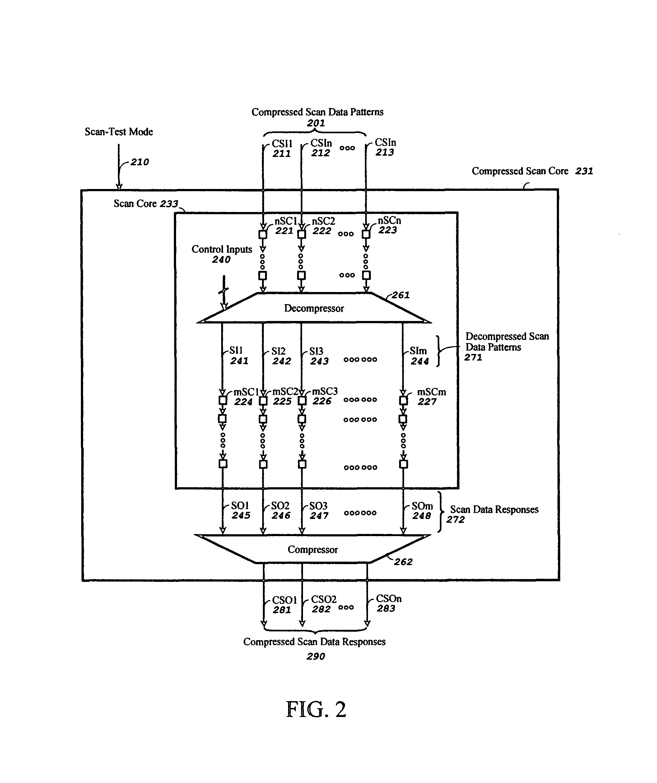
[0034]FIG. 2 shows a pipelined compressed scan test system, in accordance with the present invention, for testing scan-based integrated circuits. The Compressed Scan Core 231 comprises a Scan Core 233 followed by a Compressor 262. Furthermore, the Scan Core 233 comprises N scan chains nSC1221 to nSCn 223, M scan chains mSC1224 to mSCm 227 with the Decompressor 261 embedded within the Scan Core 233, between the N scan chains and M scan chains. The Compressed Scan Core 231 further accepts a Scan-Test Mode 210 signal, and Compressed Scan patterns 201 applied on external compressed scan inputs CSI1211 to CSIn 213 to drive the N scan chains nSC1221 to nSCn 223. The N scan chains outputs are used to drive the Decompressor 261, which also accepts Control Inputs 240 to control the Decompressor during scan-test. The Decompressor 261 reads in the Compressed Scan patterns 201 after passing through the N scan chains and generates Decompressed Scan patterns 271 on the internal M scan chain input...

second embodiment

[0037]FIG. 3 shows a pipelined compressed scan test system, in accordance with the present invention, for testing scan-based integrated circuits. The Compressed Scan Core 331 comprises a Decompressor 361 followed by a Scan Core 333. Furthermore, the Scan Core 333 comprises M scan chains mSC1324 to mSCm 327, N scan chains nSC1321 to nSCn 323 with the Compressor 362 embedded within the Scan Core 333, between the M scan chains and N scan chains. The Compressed Scan Core 331 further accepts a Scan-Test Mode 310 signal, and Compressed Scan patterns 301 applied on external compressed scan inputs CSI1311 to CSIn 313 to drive the Decompressor 361. The Decompressor 361 also accepts Control Inputs 340 to control the Decompressor 361 during scan-test. The Decompressor 361 accepts the Compressed Scan patterns 301 and generates Decompressed Scan patterns 371 on the internal scan chain inputs SI1341 to SIm 344 to drive the M scan chains mSC1324 to mSCm 327 embedded in Scan Core 333.

[0038]The M sc...

third embodiment

[0040]FIG. 4 shows a pipelined compressed scan test system, in accordance with the present invention, for testing scan-based integrated circuits. The Compressed Scan Core 431 comprises a Scan Core 434 with two intermediate decompressors Decompressor1461 and Decompressor2462 and two intermediate compressors Compressor1463 and Compressor2464 embedded in the Scan Core 434. Furthermore, the Decompressor circuit is split and pipelined among the internal scan chains using the two intermediate decompressors, Decompressor1461 and Decompressor2462. Also, the Compressor circuit is split and pipelined among the internal scan chains using the two intermediate compressors, Compressor1463 and Compressor2464. The Scan Core 434 also comprises N input scan chains nISC1421 to nISCn 422, J internal input scan chains jISC1423 to jISCj 424 embedded between the intermediate stages of the pipelined Decompressor, M scan chains mSC1425 to mSCm 426, K internal output scan chains kOSC1427 to kOSCk 428 embedde...


PUM


Abstract

A pipelined scan compression method and apparatus for reducing test data volume and test application time in a scan-based integrated circuit without reducing the speed of the scan chain operation in scan-test mode or self-test mode. The scan-based integrated circuit contains one or more scan chains, each scan chain comprising one or more scan cells coupled in series. The method and apparatus includes a decompressor comprising one or more shift registers, a combinational logic network, and an optional scan connector. The decompressor decompresses a compressed scan pattern on its compressed scan inputs and drives the generated decompressed scan pattern at the output of the decompressor to the scan data inputs of the scan-based integrated circuit. Any input constraints imposed by said combinational logic network are incorporated into an automatic test pattern generation (ATPG) program for generating the compressed scan pattern for one or more selected faults in one-step.

Description

RELATED APPLICATION DATA[0001]The present application is a continuation-in-part of application Ser. No. 11 / 122,244 filed May 5, 2005 now U.S. Pat. No. 7,590,905 which is hereby incorporated by reference and for which priority is claimed, which application claims the benefit of U.S. Provisional Application No. 60 / 573,341 filed May 24, 2004.[0002]The present application is also related to application Ser. No. 10 / 339,667 filed Jan. 10, 2003.FIELD OF THE INVENTION[0003]The present invention generally relates to the field of logic design and test using design-for-test (DFT) techniques. Specifically, the present invention relates to the field of logic test and diagnosis for integrated circuits using scan or built-in self-test (BIST) techniques.BACKGROUND[0004]Different scan compression techniques have emerged for compressing scan patterns, generated using automatic test pattern generation (ATPG) tools, for reducing both test application time and test data volume. Current scan compression ...

Claims


Application Information

Patent Timeline
Patent Type & Authority Patents(United States)
IPC IPC(8): G01R31/3177G01R31/40
CPCG01R31/318547
Inventor WANG, LAUNG-TERNG L.-T.TOUBA, NUR A.SHEU, BORYAUWU, SHIANLINGJIANG, ZHIGANG
Owner SYNTEST TECH
Why Eureka
Try Eureka