Ventilation systems and methods employing aerosol generators

a technology of generators and aerosols, applied in the direction of valves, respirators, mechanical devices, etc., can solve problems such as certain challenges, and achieve the effects of minimizing dilution effects, quiet operation, and small siz

Active Publication Date: 2011-05-24
NOVARTIS AG
View PDF523 Cites 14 Cited by
  • Summary
  • Abstract
  • Description
  • Claims
  • Application Information

AI Technical Summary

Benefits of technology

[0007]In one embodiment of the invention, the pressure-generating circuit may comprise a conduit that couples a flow generator that produces a high volume flow of gas through the conduit with a pressure-regulating device that maintains the CPAP. The respiratory circuit provides a lower-volume positive pressure air flow from the pressure generating-circuit to the patient interface device for inhalation by the patient. The respiratory circuit may comprise a conduit connected at one end to the pressure-generating circuit and at the other end to the patient interface device. In one particular embodiment, the respiratory circuit comprises a flexible tube having a small diameter, e.g. an outside diameter of 5 mm or less, connected at one end, e.g. through a “T” or “Y” shaped junction unit, to a larger flexible tube comprising the pressure-generating circuit, and at the other end to the patient interface device. This arrangement allows the patient to move his / her head freely without disconnecting the patient interface device from the patient. Alternatively, the respiratory circuit may comprise a gas conduit contained within the patient interface device itself.
[0008]The nebulizer is coupled to the respiratory circuit and is adapted to emit an aerosolized medicament directly into the portion of the total gas flow that is inhaled by the patient, preferably in the direct vicinity of the patient's nose, mouth or artificial airway, thereby eliminating the dilution effect caused by introducing the aerosolized medicament into the high-volume gas flow of the pressure-generating circuit. Nebulizers suitable for the practice of the present invention generally comprise a reservoir for holding a liquid medicament to be delivered to a patient's respiratory system, a vibrating aperture-type aerosol generator for aerosolizing the liquid medicament and a connector for connecting nebulizer to the respiratory circuit. Particularly preferred nebulizers of the invention are small and light-weight, for example having a net weight (without liquid) of 5 gms or less, preferably 3 gms or less, and have a connector adapted to attach to the weaker smaller diameter tube making up the respiratory circuit. Such “miniature” nebulizers may have a small reservoir that holds one unit dose of medicament, e.g. less than 4 ml of liquid, and a light-weight aerosol generator, e.g. on the order of about 1 gm in weight. In addition, preferred nebulizers are quiet in operation, e.g. producing less than 5 decibels of sound pressure, so that they can conveniently be placed very close to the patient.
[0010]The present invention provides a number of benefits. The nebulizer of the present invention is located outside the primary high flow pressure-generating circuit of the pressure-assisted breathing system, thereby minimizing the dilution effect that would occur if the aerosolized medicament is introduced into the total (much greater) flow of gas passing through the primary pressure-generating circuit. In addition, because of its small size and quiet operation, the nebulizer may be located in very close proximity to the patient's airway, thereby decreasing the distance which the medicament must travel and further increasing the efficiency of the system.
[0011]Due to the increased efficiency of the present invention, the reservoir of the nebulizer may be sized to accommodate a smaller amount of medicament. For example, the reservoir of the nebulizer may have a capacity equal to a single unit dose of medicament, i.e. an amount sufficient for one treatment, and substantially all of the medicament may be delivered to the patient without the need to replenish the reservoir. This is particularly beneficial in respiratory therapies that utilize phospholipid surfactants since these medicaments are scarce, expensive and, because of their high viscosity, difficult to deliver. The present invention may also eliminate the need to pump medicament from an outside container to the nebulizer, although in some applications of the invention this may be desirable.

Problems solved by technology

Use of a nebulizer in connection with a pressure-assisted breathing system having a positive pressure-generating circuit with continuous flow through the circuit, such as many CPAP and Bi-level systems, presents certain challenges.

Method used


Image

  • Ventilation systems and methods employing aerosol generators
  • Ventilation systems and methods employing aerosol generators
  • Ventilation systems and methods employing aerosol generators

Examples


Embodiment Construction

[0019]The following detailed description is directed to a CPAP embodiment of the invention for illustrative purposes only, it being understood that the invention is not limited to such embodiment and can be applied to other pressure-assisted breathing systems.

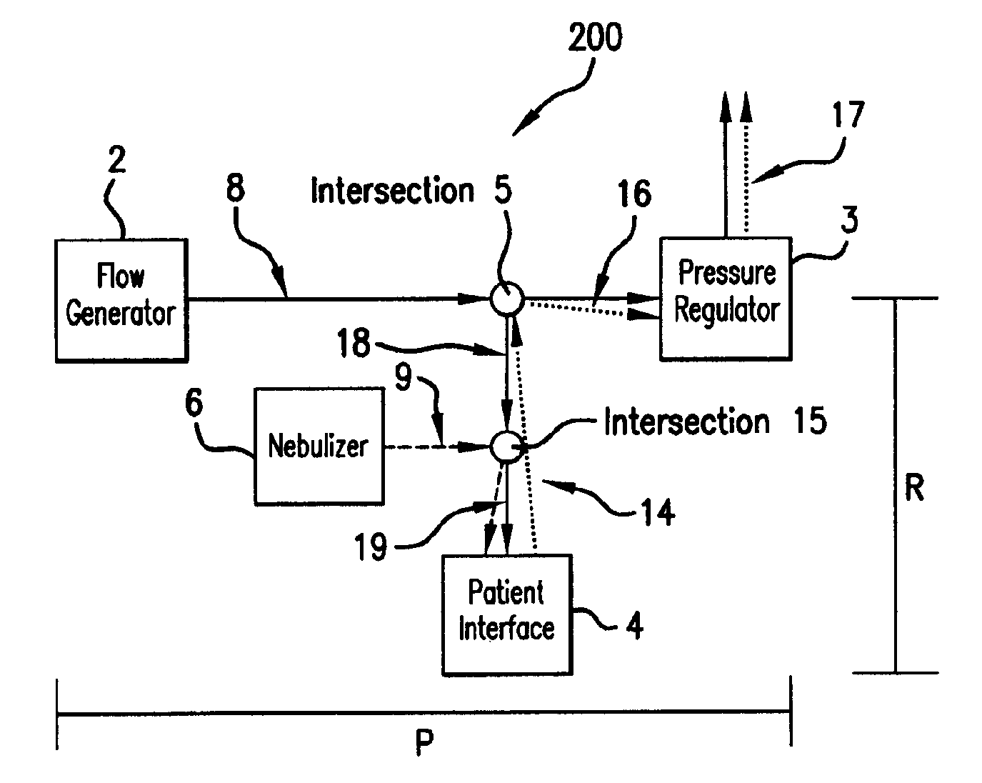
[0020]FIG. 1 of the drawings is a schematic illustration of a CPAP system 100 employing a nebulizer. The CPAP system 100 includes a primary pressure-generating circuit P and a respiratory circuit R. Circuit P includes a flow generator 2 in fluid communication with a pressure-regulating device 3. Respiratory circuit R includes a patient interface device 4 in fluid communication with circuit P at intersection 5. Nebulizer 6 is in fluid communication with circuit P at intersection 7 upstream to intersection 5. In operation, a high volume flow of gas 8 is introduced into circuit P from flow generator 2 and passes to and through pressure-regulating device 3 so as to maintain a positive pressure in the system. Nebulizer 6 emits an ae...


PUM


Abstract

A pressure-assisted breathing system comprises a pressure-generating circuit for maintaining a positive pressure within the system, and a patient interface device coupled to a patient's respiratory system. A respiratory circuit is positioned between the pressure-generating circuit and the patient interface device and a nebulizer is coupled to the respiratory circuit.

Description

BACKGROUND OF THE INVENTION[0001]This invention relates to apparatus and methods for delivering medication to the respiratory system of a patient through an invasive or noninvasive pressure-assisted breathing system. More specifically, one aspect of the invention is directed to apparatus and methods for coupling an aerosol generator (nebulizer) with a continuous positive pressure airway (“CPAP”) or bi-level positive airway pressure (“Bi-level”) system. The use of CPAP and Bi-level systems and therapies are conventional forms of non-invasive ventilation treatment for respiratory disorders in adults, e.g. obstructive sleep apnea and respiratory insufficiency, and in children, e.g. abnormal breathing resulting from small or collapsible airways, small lung volumes, muscle weakness, respiratory distress syndrome, persistent obstruction following surgery, etc. Systems that utilize an endotracheal or tracheotomy tube are examples of invasive pressure-assisted breathing systems. As used her...

Claims


Application Information

Patent Timeline
Patent Type & Authority Patents(United States)
IPC IPC(8): A61M16/00A61M16/14A61M11/00A61M15/00A61M16/08
CPCA61M11/005A61M16/0833A61M16/08A61M15/0085
Inventor FINK, JAMESIVRI, EHUD
Owner NOVARTIS AG
Why Eureka
Try Eureka