Hip joint prosthesis with a shaft to be inserted into the femur

a technology of hip joint and prosthesis, which is applied in the direction of prosthesis, femoral head, joint implants, etc., to achieve the effect of rapid bone incorporation and rapid accumulation of bon

Active Publication Date: 2011-05-24
WALDEMAR LINK GMBH & CO
View PDF35 Cites 11 Cited by
  • Summary
  • Abstract
  • Description
  • Claims
  • Application Information

AI Technical Summary

Benefits of technology

[0009]The effect of the invention is that, very quickly after the operation, bone cells develop in immediate proximity to and in connection to the prosthesis surface. The result of this is that relative movements between the bone surface and the bone do not initially cause formation of a gap or an intermediate connective tissue layer which makes subsequent intimate connection more difficult or impossible. By virtue of the invention, there is a more rapid accumulation of bone on the trochanteric surface of the prosthesis and more rapid incorporation of bone into the pores and recesses thereof, so that the trochanteric area of the bone quickly achieves a permanent connection to the prosthesis and, as a result of this, is involved in the transmission of forces. By contrast, on the other surface areas, the connection to the bone is achieved only to the previously expected extent. Outside the trochanteric area, which is readily accessible in the event of follow-up surgery and therefore does not cause any problems even when the bone is very strongly bound, the physician, when performing follow-up surgery, therefore finds exactly those conditions with which he is already accustomed.
[0010]The part of the surface containing the osteoinductive substance expediently comprises pores or undercuts in relation to the lateral direction, so that the bone substance formed as a result of the osteoinduction can not only adhere to the surface but can also anchor onto it with a form fit.
[0011]In the middle of the trochanteric part of the bone, the spongy substance is sometimes less dense than it is near the cortex. For this reason, those portions of the osteoinductively finished surface areas of the prosthesis that point in the ventral and dorsal directions are preferably situated at a certain distance from the mid-plane of the bone and nearer the cortex. Therefore, the part of the prosthesis forming these surface areas ought not to be too thin in the AP direction. Its thickness, and thus the distance between said dorsal and ventral surface areas, is expediently over 6 mm, and more advantageously over 9 mm to approximately 15 mm.
[0012]The growth of fresh bone cells onto the prosthesis surface can be promoted by a press-fit of the surface areas in question. It is therefore expedient if the surfaces in question, and their mating surfaces, are made wedge-shaped in the direction in which the prosthesis is inserted into the bone, and if the rasp assigned to the prosthesis, and used to shape the receiving space for the prosthesis shaft, is provided with slightly smaller cross-sectional dimensions so that, when the prosthesis shaft is pushed into the space formed by the rasp, the surface areas in question displace bone substance.

Problems solved by technology

However, it has been found that, because of the constant alternating loading, mechanical tension anchors of this kind quickly come loose and therefore are effective only for a short time.
They lead to a very intimate connection of the prosthesis surface with the bone, which may be undesirable in the event of follow-up surgery because removal of the prosthesis from the bone may be impeded by this.

Method used


Image

  • Hip joint prosthesis with a shaft to be inserted into the femur
  • Hip joint prosthesis with a shaft to be inserted into the femur
  • Hip joint prosthesis with a shaft to be inserted into the femur

Examples


Embodiment Construction

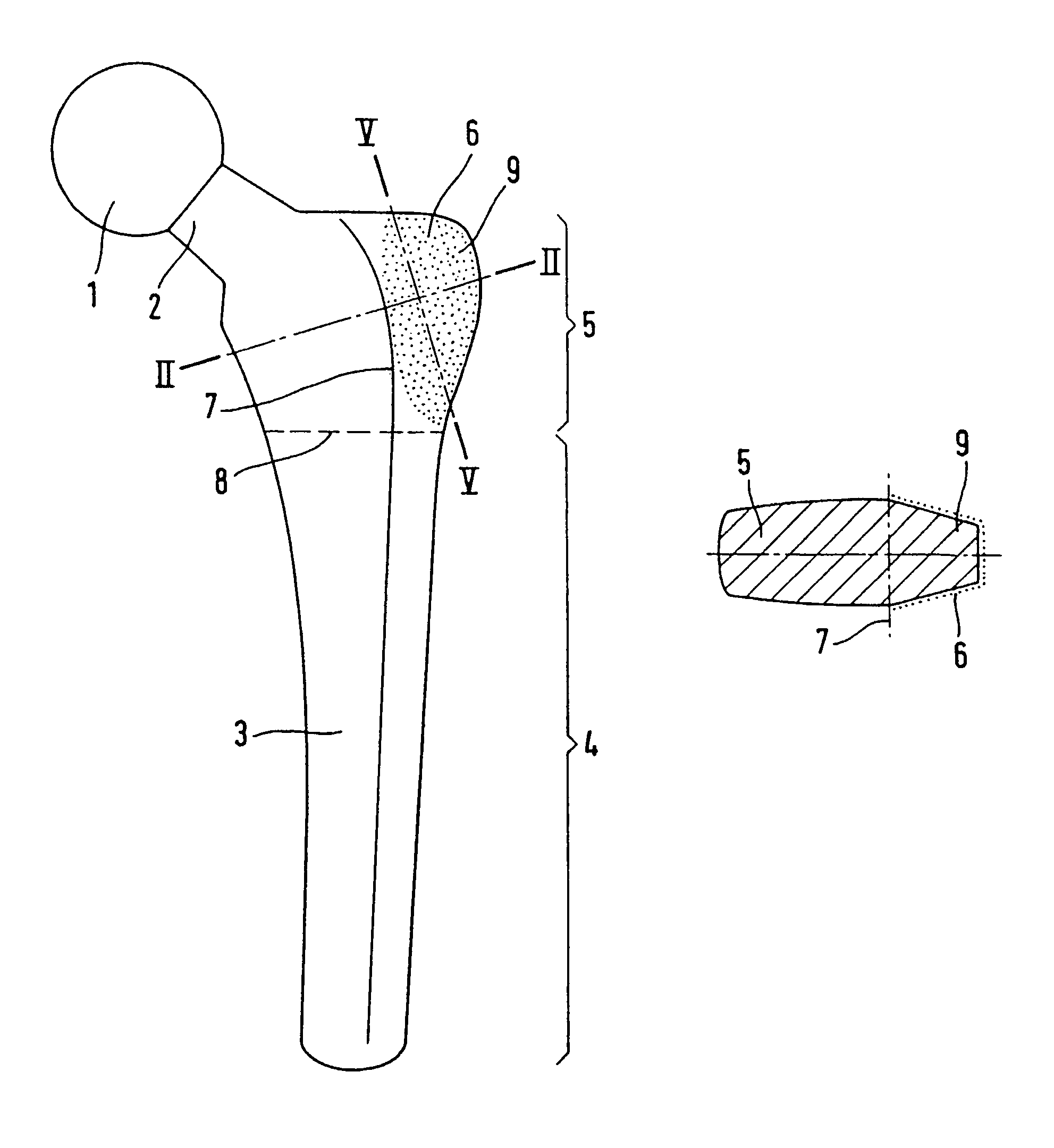
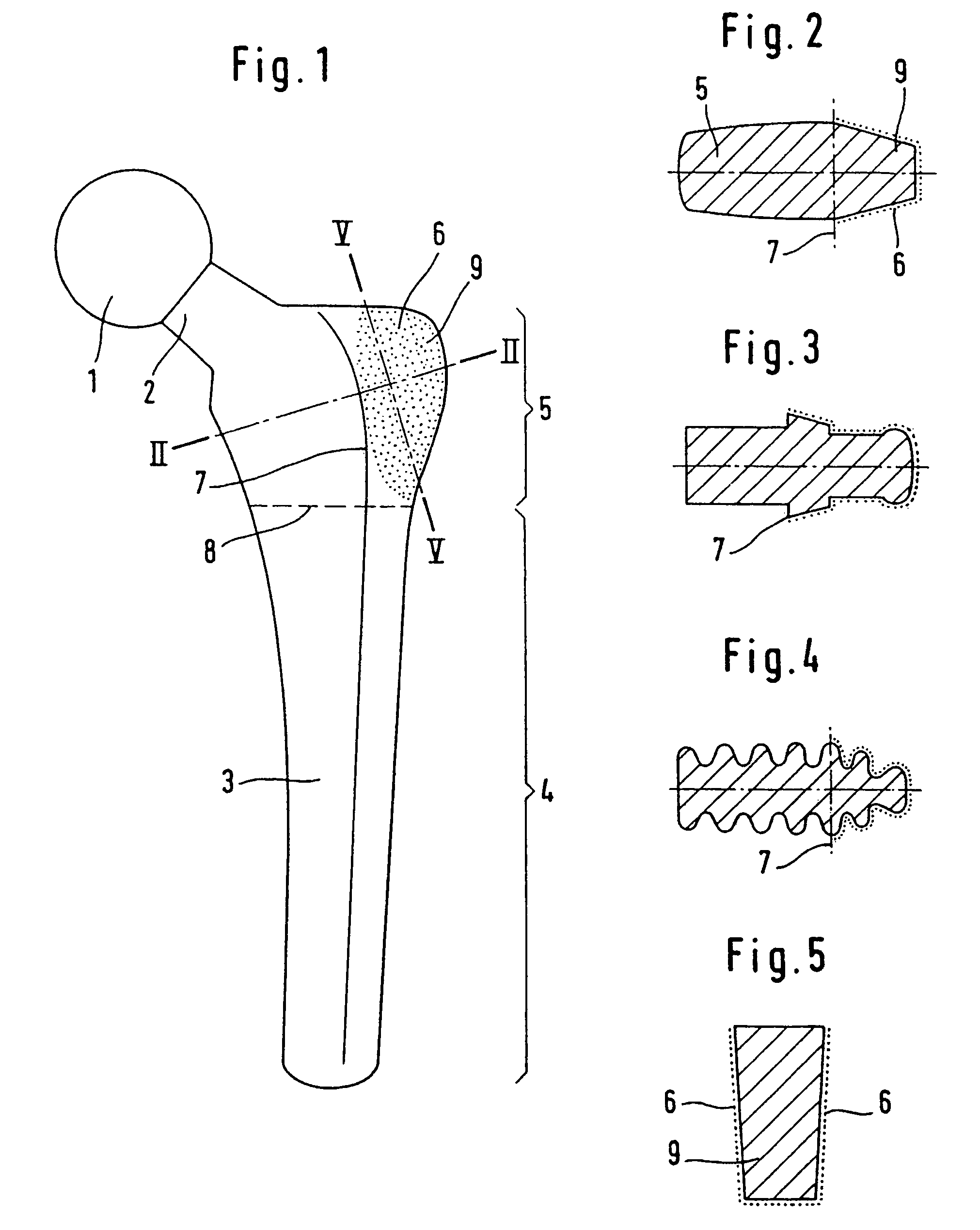
[0020]The hip prosthesis according to FIG. 1 comprises a joint head 1, and a neck 2 which has a shaft 3. The latter has a diaphyseal portion 4 to be anchored in the diaphysis of the bone, and a metaphyseal portion 5 to be anchored in the metaphysis of the bone. The diaphyseal portion is dimensioned such that it ensures primary anchoring of the shaft in the diaphysis of the femur. The person skilled in the art will see, from looking at FIG. 1, how the prosthesis will lie in the bone, and he or she will therefore also know where the border 8 between the diaphyseal and metaphyseal portions of the prosthesis lies.

[0021]Whereas the diaphyseal portion 4 of the shaft can bear on the strong cortical bone of the diaphysis and effect primary anchoring there, the metaphyseal portion lies mainly in the spongy bone tissue of the metaphysis.

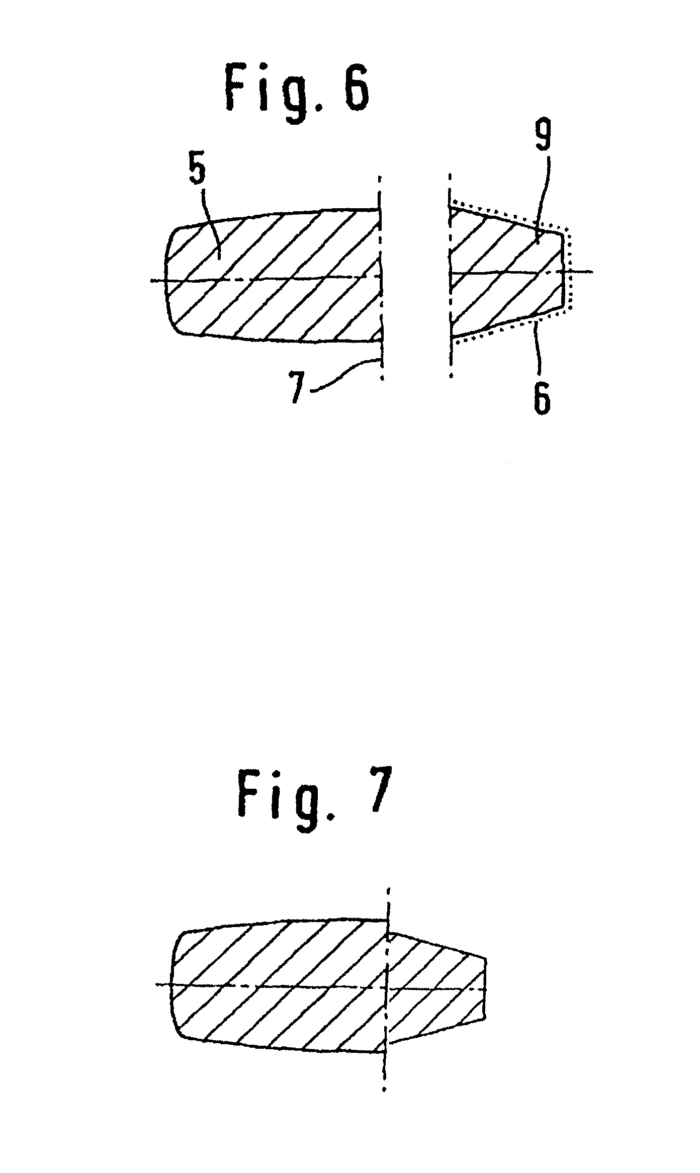
[0022]FIG. 2 shows a location 7 having the greatest dimension of the shaft 3 in the AP direction (antero-posterior). The connection of the locations of maximu...


PUM

PropertyMeasurementUnit
thicknessaaaaaaaaaa
thicknessaaaaaaaaaa
thicknessaaaaaaaaaa

Abstract

A hip-joint prosthesis includes a shaft which is configured to be inserted into the femur and whose surface has an osteoinductive finish. This finish is provided exclusively in the metaphyseal portion of the shaft and laterally from the line delineating the maximum antero-posterior dimension of the shaft cross section. This ensures a better involvement of the metaphyseal spongiosa in the flow of forces, without compromising the ability to perform follow-up surgery on the prosthesis.

Description

REFERENCE TO RELATED APPLICATIONS[0001]This application is a national stage application under 35 USC 371 of International Application No. PCT / EP2005 / 008513, filed Aug. 5, 2005, which claims priority from European Application No. 04 018 714.8, filed Aug. 6, 2004, the entire contents of which are incorporated herein by reference.FIELD AND BACKGROUND OF THE INVENTION[0002]The spongy bone tissue in the metaphysis of the femur includes a complicated structure of bone trabeculae via which the parts of the bone subjected to compression loads and tensile loads at the femoral neck, the greater trochanter, the lesser trochanter and the diaphysis are connected in a manner transmitting compression and tension. In their totality, they form continuous tension and compression trajectories (Farbatlanten der Medizin [Colour Atlas of Medicine], Volume 7: Locomotor apparatus I., published by Thieme Verlag, Stuttgart, 1992). When the shaft of a hip-joint prosthesis is inserted, the primary tension traj...

Claims


Application Information

Patent Timeline
Patent Type & Authority Patents(United States)
IPC IPC(8): A61F2/32
CPCA61F2/367A61F2/30767A61F2/30739A61F2310/00976A61F2/36A61F2/3662A61F2/3676A61F2002/3011A61F2002/30112A61F2002/30136A61F2002/30138A61F2002/30158A61F2002/30159A61F2002/30322A61F2002/3611A61F2002/3625A61F2230/0002A61F2230/0004A61F2230/0017A61F2230/0026A61F2230/0028A61F2250/0026A61F2310/00796
Inventor LINK, HELMUT D.
Owner WALDEMAR LINK GMBH & CO
Why Eureka
Try Eureka