Hydrogen reservoir and process for filling a hydrogen reservoir

a technology of hydrogen reservoir and hydrogen reservoir, which is applied in the direction of liquid handling, separation process, packaged goods type, etc., can solve the problems of comparatively easy handling of solid reservoirs, storage materials that can only absorb approximately 2% of their own weight in hydrogen at room temperature, etc., to speed up reaction kinetics, improve utilization of empty volume, and improve purposeful temperature control

Inactive Publication Date: 2011-05-24
DAIMLER AG
View PDF27 Cites 18 Cited by
  • Summary
  • Abstract
  • Description
  • Claims
  • Application Information

AI Technical Summary

Benefits of technology

[0012]In this way, the porous body advantageously assumes multiple functions. On the one hand, it serves as a mechanical support for the container filled with storage material, while on the other hand it serves as a flow path for hydrogen from the storage material out of the housing and / or from a housing inlet to the storage material. In addition, it serves as a heat conductor, in order to cool the storage material during filling, if it is heated by exothermic ad- or absorption, or to heat it during emptying, in order to provide heat of reaction for endothermic desorption and to achieve purposeful release of hydrogen from the storage material. Any desired storage material may be used. The hydrogen reservoir may be filled within just a few minutes. The double enclosure of the storage material provides for an inexpensive and safe tank construction. A filling station infrastructure for filling hydrogen tanks may be simplified considerably over high pressure reservoirs operating at several hundred bar and conventional solid tanks. Under service conditions, coupling with a fuel cell system with evaporative cooling is particularly favorable.
[0014]Because the container may be embedded in the preferably cup-shaped porous body, stable accommodation of the storage material is achieved. This makes it possible to reliably prevent the generally pulverulent storage material from being entrained out of the hydrogen reservoir. The storage material is safely encapsulated in the container and retained by the porous body. In comparison with known arrangements, in which pulverulent storage material is retained in a finely dispersed manner in a metal foam matrix or between aluminum lamellae, production is additionally simplified. The container is filled, closed and embedded in the porous body. Mechanical forces due to expansion of the storage material, for instance due to storage of hydrogen, during charging with hydrogen may be absorbed by the container and / or by the porous body. The storage material may expand by up to 20% during hydrogen storage. The cup-shaped container is preferably closed by a lid with an interference fit. In this respect, the internal diameter of the lid is made to be somewhat smaller than the external diameter of the cup. The lid is heated and positioned on the colder cup in the expanded, heated state. During cooling the lid shrinks such that the lid is joined stably to the cup. Cup and lid are particle-tight when closed.
[0015]In at least one reservoir axis, a plurality of units may advantageously be arranged adjacent one another. The size of the reservoir may readily be changed at the design stage by stacking the units and / or arranging them side by side. The units may be positioned in a modular manner adjacent one another widthwise and / or heightwise. The modular construction with the preferred units facilitates the manufacture of hydrogen reservoirs in accordance with different objectives.
[0016]Advantageously, the units may be arranged in such a way that a lid of the container of the one unit supports the base of the porous body of the next unit in the stack direction. A staggered arrangement is also possible, in order to improve flow control. In this way, the container is in all-round contact with the porous body and is held secure thereby while also being held in intimate thermal contact with the heat-conducting porous body. The housing is preferably completely filled with such units and is therefore very robust with respect to vibrations or exposure to impacts. Furthermore, degradation, caused by thermal overheating of catalysts associated with the storage medium, preferably titanium-based catalysts in storage materials based on alanate and / or on amide / hydride and / or on hydridoborates, may be avoided.
[0019]To improve utilization of the empty volume in the porous body and to speed up reaction kinetics, the pressure may be selected to be high during filling, for example 50 bar or more, in accordance with the selected wall thickness of the housing of the hydrogen reservoir. Hydrogen gas may be stored under pressure in the porous body, in addition to the hydrogen in the storage material.
[0020]In a favorable configuration, a temperature control agent line may be arranged inside the housing, which line may be designed in particular for connection with a vehicle cooling system. In this way, purposeful temperature control may be improved during filling and / or emptying of the hydrogen reservoir.

Problems solved by technology

Since these hydrogen reservoirs require neither extreme temperatures nor high pressures, solid reservoirs are comparatively uncomplicated to handle.
However, these storage materials can only absorb approximately 2% of their own weight in hydrogen at room temperature.

Method used


Image

  • Hydrogen reservoir and process for filling a hydrogen reservoir
  • Hydrogen reservoir and process for filling a hydrogen reservoir
  • Hydrogen reservoir and process for filling a hydrogen reservoir

Examples


Embodiment Construction

[0032]In the figures, elements which have the same function are labeled with the same reference signs.

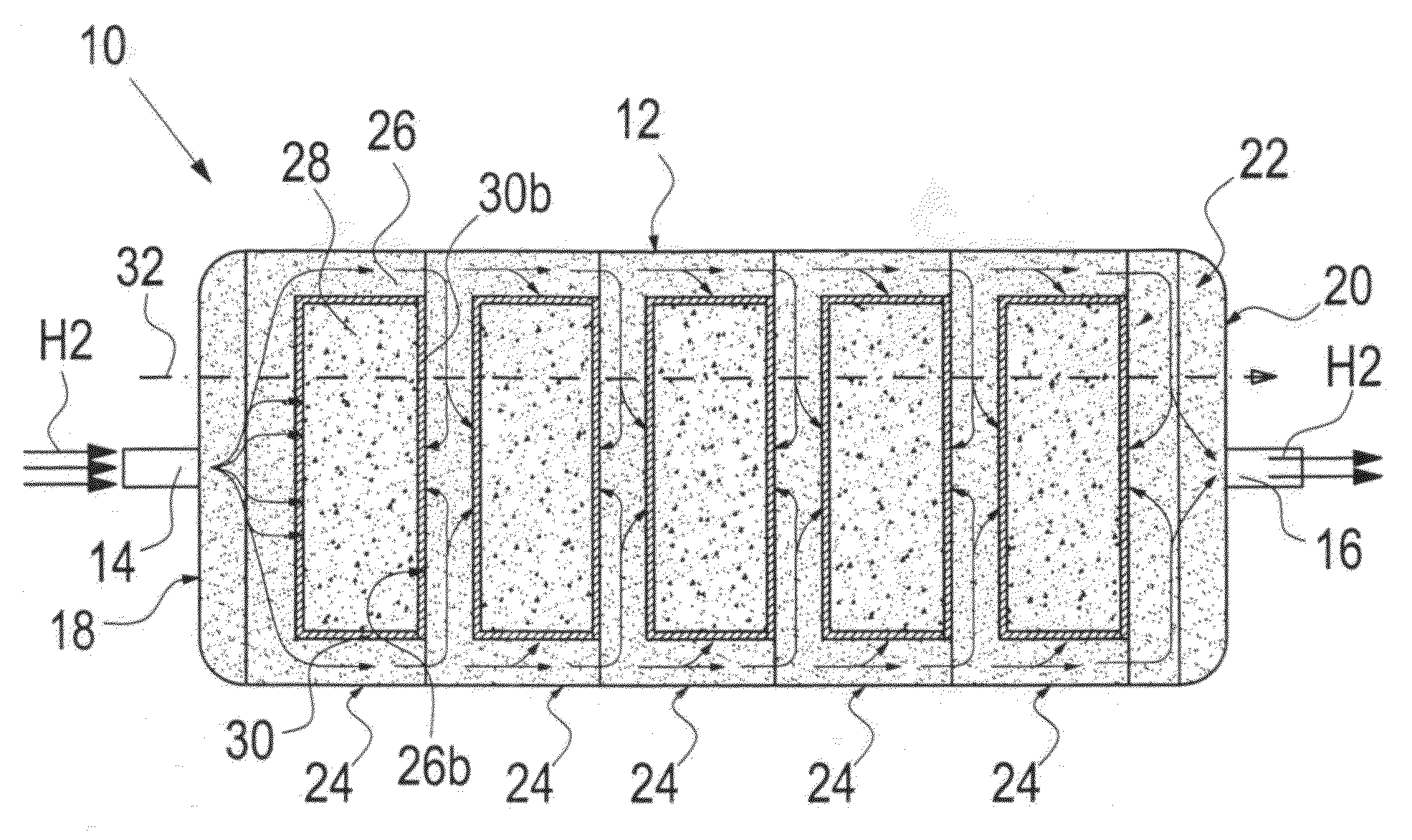
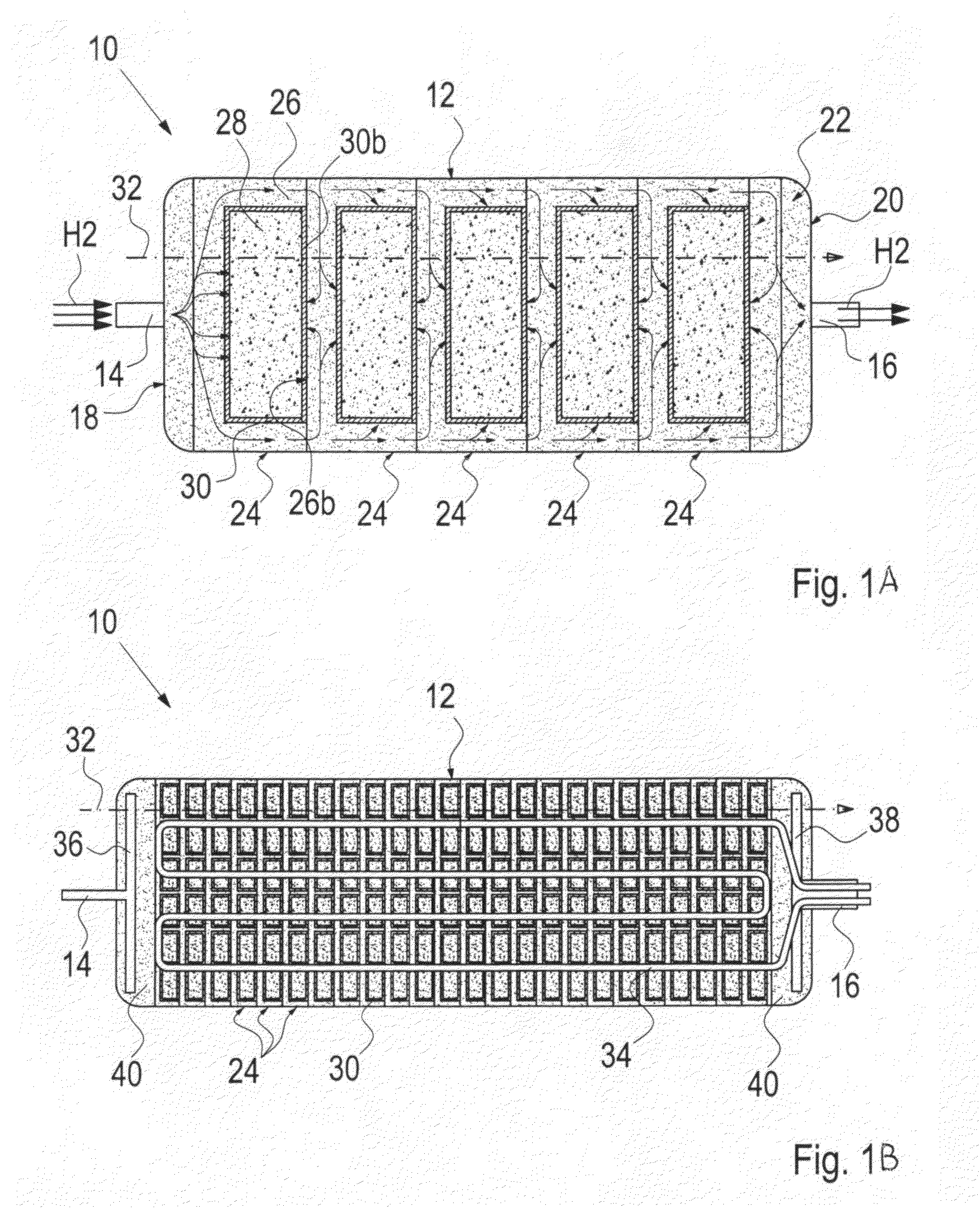
[0033]Two configurations of a hydrogen reservoir 10 according to the invention are shown in FIGS. 1A and 1B. The hydrogen reservoir 10 is configured as a type of storage pipe.

[0034]The hydrogen reservoir 10 comprises a housing 12, in which a plurality of units 24 are arranged adjacent one another in a row along a reservoir axis 32, filling the housing 12 between an inlet 14 at one end 18 and an outlet 16 at another end 20 of the housing 12. The reservoir axis 32 corresponds to the stack direction of the units 24.

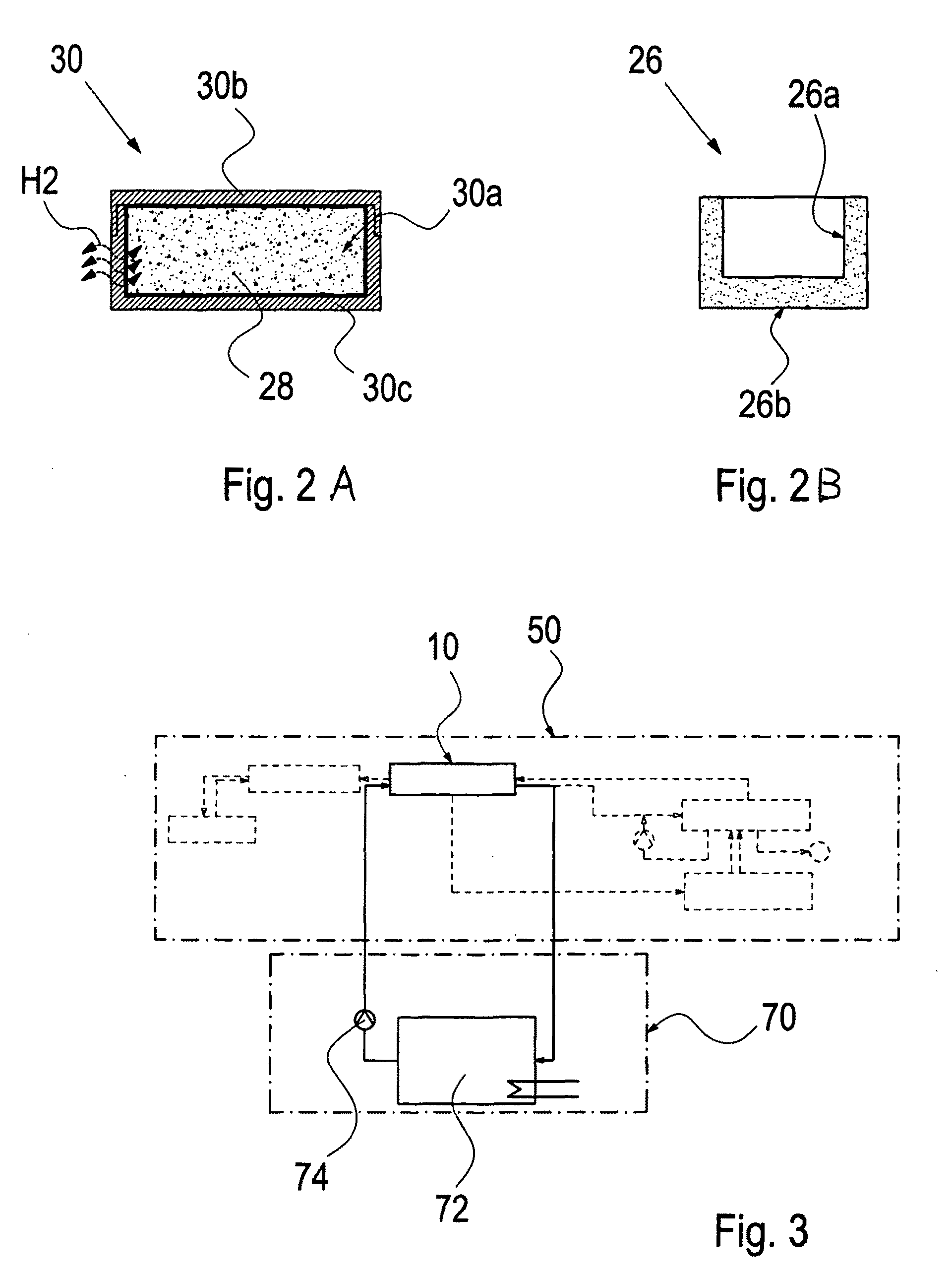
[0035]As is additionally explained in greater detail in FIGS. 2A and 2B, each unit 24 consists of a cup-shaped porous body 26 with a recess 26a and a preferably closed base 26b. A container 30 comprising a cup-shaped body 30c closable with a lid 30b and preferably made from gas-permeable sintered metal is inserted into the recess 26a. The lid 30b may be adhesively bonded, so...


PUM

PropertyMeasurementUnit
pressureaaaaaaaaaa
pressureaaaaaaaaaa
pressureaaaaaaaaaa

Abstract

In a hydrogen reservoir having a housing with a hydrogen storage material arranged in the housing for absorbing and releasing hydrogen as needed, the hydrogen reservoir includes at least one unit having a porous body surrounding a container in which the hydrogen storage material is contained and a method is provided for charging the hydrogen reservoir with hydrogen from a hydrogen filling stations.

Description

[0001]This is a Continuation-In-Part Application of pending International patent application PCT / EP2007 / 002794 filed Mar. 29, 2007 filed and claiming the priority of German patent application 10 2006 020 394.1 filed Apr. 28, 2006.BACKGROUND OF THE INVENTION[0002]The invention relates to a hydrogen reservoir and to a process for filling a hydrogen reservoir in which the hydrogen is absorbed and from which it can be released when desired.[0003]It is known to store hydrogen by storing it either in gaseous form in pressure tanks at several hundred bar overpressure or in liquid form at cryogenic temperatures in special cooling tanks.[0004]In addition, solid reservoirs are known, in which the hydrogen is absorbed, retained in the atomic structure thereof and released again when the temperature of the reservoir is increased. Since these hydrogen reservoirs require neither extreme temperatures nor high pressures, solid reservoirs are comparatively uncomplicated to handle. Such hydrogen rese...

Claims


Application Information

Patent Timeline
Patent Type & Authority Patents(United States)
IPC IPC(8): F17C11/00
CPCC01B3/0005B01J2208/00141Y02E60/327B01J2219/1923F17C11/005Y02E60/32Y02P20/129
Inventor GOLZ, DANIELKELLER, CLAUDEPOLIFKE, WOLFGANGSCHMIDT-IHN, EBERHARDWENGER, DAVID
Owner DAIMLER AG
Why Eureka
Try Eureka