Carbonated beverage aseptic filling system, beverage filling system, and cip processing method

Active Publication Date: 2021-08-26
DAI NIPPON PRINTING CO LTD
View PDF0 Cites 2 Cited by
  • Summary
  • Abstract
  • Description
  • Claims
  • Application Information

AI Technical Summary

Benefits of technology

[0019]According to the present disclosure, the CIP processing time can be shortened in a

Problems solved by technology

However, the rotary joint has a complicated structure and therefore a configuration of the carbonated beverage aseptic filling apparatus is likely to be complicated.
Further

Method used


Image

  • Carbonated beverage aseptic filling system, beverage filling system, and cip processing method
  • Carbonated beverage aseptic filling system, beverage filling system, and cip processing method
  • Carbonated beverage aseptic filling system, beverage filling system, and cip processing method

Examples


first embodiment

[0030]Hereinafter, a first embodiment will be explained by referring to FIGS. 1 to 3. FIGS. 1 to 3 show the first embodiment. In the respective drawings mentioned below, the same numerals are given to the same parts and the detailed explanation will be partially omitted in some cases.

Carbonated Beverage Aseptic Filling System

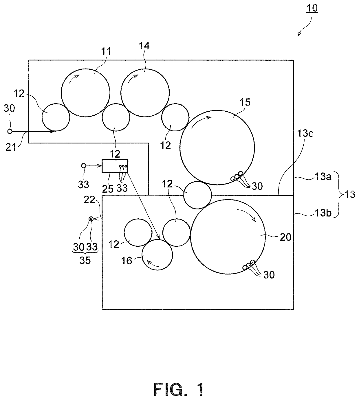
[0031]First, the entire carbonated beverage aseptic filling system according to the present embodiment will be explained by referring to FIG. 1.

[0032]A carbonated beverage aseptic filling system 10 shown in FIG. 1 is a system for filling a bottle (container) 30 with contents composed of an aseptic carbonated beverage. The bottle 30 can be fabricated by performing biaxial stretching blow molding on a preform fabricated by injection-molding a synthetic resin material. As the material for the bottle 30, thermoplastic resins, particularly, PE (polyethylene), PP (polypropylene), PET (polyethylene terephthalate) or PEN (polyethylene naphthalate) are preferably used. M...

second embodiment

[0092]Next, a second embodiment will be explained by referring to FIGS. 4 to 10. FIGS. 4 to 10 show the second embodiment. The parts in FIGS. 4 to 10 that correspond to those in the first embodiment will be given the same numerals and their detailed explanation will be omitted. The second embodiment will be explained below by mainly referring to differences from the first embodiment.

Beverage Aseptic Filling System

[0093]First, the entire beverage aseptic filling system according to the present embodiment will be explained by referring to FIG. 4.

[0094]A beverage aseptic filling system 110 shown in FIG. 4 is a system for serving both carbonated beverages and non-carbonated beverages, namely, an aseptic filling system capable of alternatively filling, into the bottle (container) 30, both a beverage composed of a carbonated beverage and a beverage composed of a non-carbonated beverage. In the present embodiment, an example of using a plastic bottle as the container will be explained, whi...


PUM


Abstract

A carbonated beverage aseptic filling system (10) comprises: a filling nozzle (72) for filling a carbonated beverage; a carbonated beverage filling tank (75) connected to the filling nozzle (72) via a carbonated beverage supplying pipe (73) and a counter pressure pipe (74); a snift pipe (78) connected to the filling nozzle; and an aseptic chamber (13) enclosing the filling nozzle (72), at least part of the carbonated beverage supplying pipe (73), and at least part of the counter pressure pipe (74). The carbonated beverage supplying pipe (73) and the counter pressure pipe (74) are attached to the aseptic chamber (13) by a rotary joint (77). A discharging valve (79) is provided in the snift pipe (78) inside the aseptic chamber (13), and gas from the snift pipe (78) is discharged into the aseptic chamber.

Description

TECHNICAL FIELD[0001]The present disclosure relates to a carbonated beverage aseptic filling system, a beverage filling system, and a CIP processing method.BACKGROUND ART[0002]Conventionally, a filling machine such as a filler provided in a carbonated beverage aseptic filling apparatus has been used to continuously and aseptically fill a large number of plastic bottles transported at high speed with content such as carbonated beverage.[0003]In such a carbonated beverage aseptic filling apparatus, a filling nozzle for filling a plastic bottle with carbonated beverage is disposed rotatably inside an aseptic chamber. Therefore, each of a carbonated beverage supplying pipe, a pipe for counter gas, and a pipe for snifting, etc. to be connected to the filling nozzle is attached to an aseptic chamber by means of a rotary joint (see for example Patent Literature 1).[0004]However, the rotary joint has a complicated structure and therefore a configuration of the carbonated beverage aseptic fi...

Claims


Application Information

Patent Timeline
IPC IPC(8): B67C3/08B67C3/12B67C3/22
CPCB67C3/08B67C2003/228B67C3/22B67C3/12B67C3/001B67C7/0073B67C2003/2694B67C3/10B67C3/2614B67C2003/2602
Inventor HAYAKAWA, ATSUSHI
Owner DAI NIPPON PRINTING CO LTD
Why Eureka
Try Eureka