Liquid end assembly for a handheld multichannel pipette with adjustable nozzle spacing

a multi-channel pipette and nozzle spacing technology, which is applied in the field of multi-channel pipettes, can solve the problems of inability to use a fixed 9 mm multi-channel pipette, and inability to rotate the nozzle in some ways, so as to prevent undesired rotation of the nozzle, the effect of convenient us

Active Publication Date: 2011-05-24
RAININ INSTR
View PDF7 Cites 15 Cited by
  • Summary
  • Abstract
  • Description
  • Claims
  • Application Information

AI Technical Summary

Benefits of technology

The multichannel liquid end disclosed herein matches the capability of known commercial adjustable spacing pipettes, but with several additional advantages. Nozzle spacing is adjustable, and uniform spacing is maintained as the nozzles are adjusted between a fully-retracted configuration and a fully-expanded configuration. However, a rotatable spacing adjustment knob is employed to make the adjustment, rather than a push-pull adjustment rod as employed in several of the references set forth above. In a liquid end according to the invention, the nozzle spacing adjustment mechanism employs a rotating grooved cam and nozzles that track the grooves; a guide rail prevents undesired rotation of the nozzles along with the cam. This configuration is similar to that set forth in the '832 patent, but adapted for advantageous and convenient use in a handheld pipette.
A pipette according to the invention permits easy access to standard 96-well sample plates, as well as standard 48-well and 24-well plates. Spacing can be adjusted between the traditional 9 mm spacing used in pipette tip refill packages and any other desired spacing within the pipette's range of operation.
With a pipette according to the invention, it is simple to transfer samples between multi-well plates and racks of test tubes having spacing of 14.5 mm or more from center to center. An adjustable multichannel pipette according to the invention may also accomplish gel loading at any desired pitch. An embodiment of the invention is adjustable down to 4.5 mm centers, allowing access to 384-well microplates as well as the containers discussed above.
Because of the simple, easy-to-use, adjustment knob, a pipette using a liquid end as described herein is easy to operate, does not take unnecessary lateral space, and may be used in confined environments. The lack of an exposed adjustment rod avoids accidental movement away from the desired nozzle spacing when the pipette is inadvertently touched against a surface, as may happen from time to time in ordinary laboratory operations.
To provide the advantages described herein, the liquid end also includes a spacing adjustment mechanism configured to be manipulated by a user and to cause a rotating cam to move the nozzles between multiple spacings, with uniform nozzle-to-nozzle spacing maintained at all times. This mechanism is operated via a spacing adjustment knob, which protrudes very little from the side of the housing of the liquid end. Various embodiments also include stop mechanisms to ensure a desired maximum nozzle spacing is not exceeded, or to allow a desired setting to be reached very easily by noting the tactile resistance offered by the stop mechanism.

Problems solved by technology

However, it will be noted that this fixed nozzle configuration can be limiting in some ways.
It is not possible with a fixed 9 mm multichannel pipette to transfer liquid directly from a 96-well plate to a rack of test tubes that are spaced wider than 9 mm apart.
In the latter case, performance may be impaired, as the unused nozzles may get in the way.
This allows for unequal spacing between adjacent nozzles, but has the disadvantage of requiring each individual nozzle to be manually positioned and locked into place each time a change of spacing is desired.
This is a slow and meticulous operation; it can lead to inefficiencies in pipetting operations.
Moreover, the actuating rod that extends from a side of the pipette's housing may limit the ability of the pipette to be used in confined spaces.
For the reasons set forth above, the linear actuation rod is not ideal, in that it may prevent the use of the pipette in confined spaces.
Moreover, it may be subject to accidental movement simply by tapping the end of the rod inadvertently against any surface.
The '832 patent is directed to a robotic liquid handling apparatus, however, and does not illustrate how its concepts may be employed in a handheld device.

Method used


Image

  • Liquid end assembly for a handheld multichannel pipette with adjustable nozzle spacing
  • Liquid end assembly for a handheld multichannel pipette with adjustable nozzle spacing
  • Liquid end assembly for a handheld multichannel pipette with adjustable nozzle spacing

Examples


Embodiment Construction

The invention is described below, with reference to detailed illustrative embodiments. It will be apparent that a system according to the invention may be embodied in a wide variety of forms. Consequently, the specific structural and functional details disclosed herein are representative and do not limit the scope of the invention.

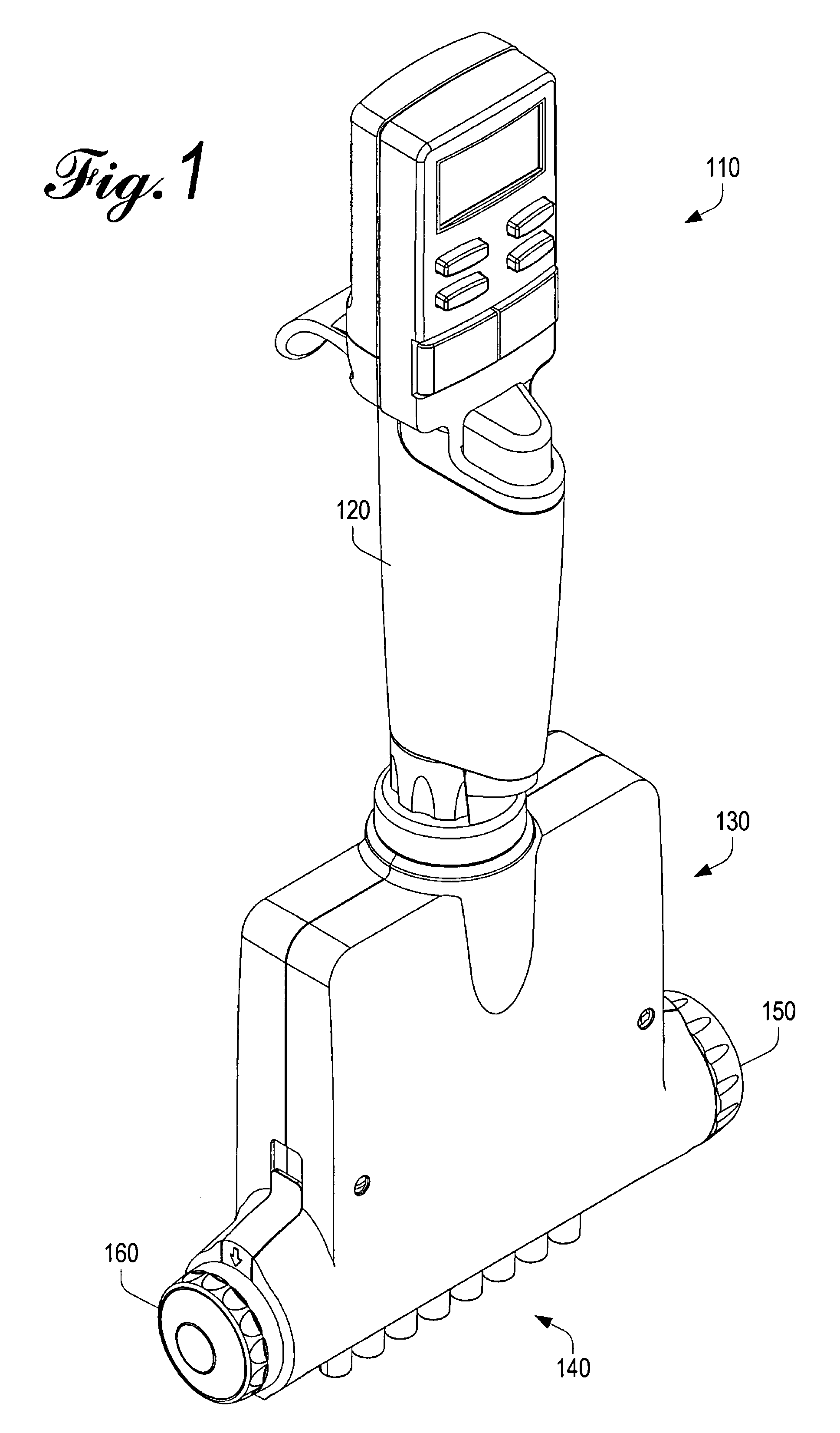
Referring initially to FIG. 1, an electronic pipette 110 similar to one from the EDP3-Plus line of pipettes from Rainin Instrument, LLC, is illustrated. The pipette 110 includes a hand-holdable body 120 which contains a drive mechanism that acts axially within the body. In the illustrated pipette 110, a motor drives a shaft up and down within the body 120, and this movement is transferred to a liquid end assembly 130.

Although FIG. 1 illustrates an electronic pipette, it will be recognized that manually-driven pipettes may also be used. In such cases, pressure upon a plunger button will drive a shaft up and down and the same movements will be transferred to...


PUM


Abstract

A handheld multichannel pipette includes multiple fluid-handling nozzles and a rotary adjustment mechanism for adjusting the width of a pattern of nozzles while maintaining equal spacing between pairs of nozzles. Embodiments of the adjustable-spacing multichannel pipette include an adjustable stop mechanism.

Description

BACKGROUND OF THE INVENTIONThe invention relates to multichannel pipettes for drawing volumes of liquid and subsequently discharging precise volumes of the drawn liquid. More particularly, the invention relates to multichannel air-displacement pipettes in which disposable tips typically contain the drawn liquid, and an air buffer separates the drawn liquid from multiple piston and cylinder structures typically utilized for drawing and discharging the liquid, so as to prevent contamination of the primary operational elements of the pipette. Specifically, the invention is directed to a multichannel liquid-end assembly for an air-displacement pipette, wherein the spacing between nozzles in the liquid end assembly is easily adjusted by a rotary mechanism.Traditional multichannel pipettes have been available for decades, and have permitted users to transfer fluid samples from one set of receptacles to another. Generally, such pipettes have multiple nozzles arranged in one or two evenly-s...

Claims


Application Information

Patent Timeline
Patent Type & Authority Patents(United States)
IPC IPC(8): B01L3/00G01F1/60
CPCB01L3/0217B01L3/0237B01L2300/0829B01L2300/027B01L2200/022
Inventor O'CONNELL, KENNETH P.VITALE, NICHOLAS R.
Owner RAININ INSTR
Why Eureka
Try Eureka