Piezoelectric device and liquid-ejecting head

a liquid-ejecting head and piezoelectric technology, applied in the direction of device material selection, generator/motor, printing, etc., can solve the problems of significantly reducing its performance, and deterioration of piezoelectric film, and achieve satisfactory moisture resistance, high function, and satisfactory moisture resistance

Active Publication Date: 2011-05-24
FUJIFILM CORP
View PDF11 Cites 10 Cited by
  • Summary
  • Abstract
  • Description
  • Claims
  • Application Information

AI Technical Summary

Benefits of technology

[0010]For instance, sputtering can be used to prepare a piezoelectric film having a fine columnar structure. Since this piezoelectric film having a fine columnar structure features high orientation, it is preferred for its ability to provide high piezoelectric constant. When a high electric field is applied to this piezoelectric film having a fine columnar structure and high piezoelectric constant, gaps will form in the columnar structure to increase the chance of ingress of water molecules. This eventually promotes the deterioration of the piezoelectric film. An improvement of moisture resistance is therefore an important objective to attain for the purpose of improving the durability of piezoelectric devices fitted with highly functional piezoelectric films having high piezoelectric constant.
[0011]One may think of improving the moisture resistance of a piezoelectric device by depositing a protective film in such a way as to cover the piezoelectric film. Protective films, particularly ones having low water permeability, are often dense films. Since such dense protective films have high Young's modulus and residual stress, they inhibit the action of the actuator, causing the problem of considerably reducing its performance, as by preventing it from producing the amount of displacement or force it inherently has the ability to produce.
[0012]To deal with this problem, the liquid-propelling head described in JP 2003-291343 A attempts to protect the piezoelectric element against moisture by joining the sealing substrate to the channel-forming substrate and forming the piezoelectric element holding section to seal the piezoelectric element. This design, however, requires adjustment in the alignment between the sealing substrate and the channel-forming substrate, thus presenting the problems of complicating the manufacturing process and increasing the manufacturing costs. In addition, the piezoelectric element holding section and the sealing substrate that are provided to seal the piezoelectric element add to the overall thickness, which in turn increases the overall size of the liquid-propelling head.
[0013]According to the approach described in JP 10-226071 A, a window is formed in the insulator layer except in part of the periphery of the upper surface of the upper electrode, the window being larger than the area of connection between the upper electrode and the electrically conductive pattern and accounting for the most part of the displacement region of the layer of piezoelectric element and this effectively prevents the insulator layer from interfering with the displacement of the layer of piezoelectric element. In this design, the region other than the periphery of the upper surface of the layer of piezoelectric element and where no insulator layer is formed is designated the window; in this window region, the upper electrode formed on the layer of piezoelectric element is exposed to the outside of the device. According to JP 10-226071 A, this upper electrode is formed of a dense film of platinum or the like.
[0016]A particular object of the present invention is to provide a highly functional piezoelectric device having satisfactory moisture resistance that has a piezoelectric film as deposited by vapor phase deposition such as sputtering to have high piezoelectric constant and which yet is capable of effectively preventing the ingress of moisture into the piezoelectric film. Another specific object of the present invention is to provide a liquid-ejecting head that includes this piezoelectric device.
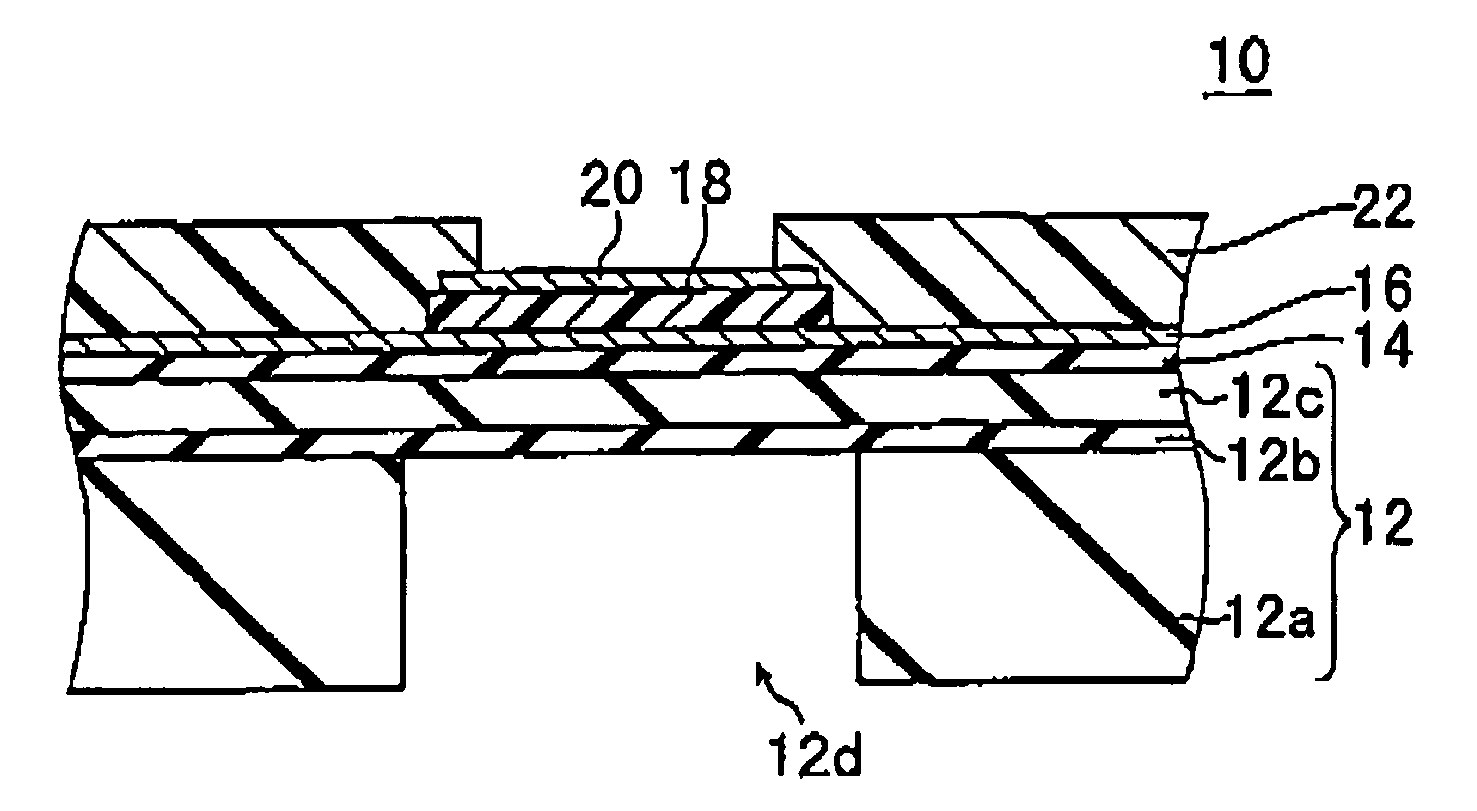
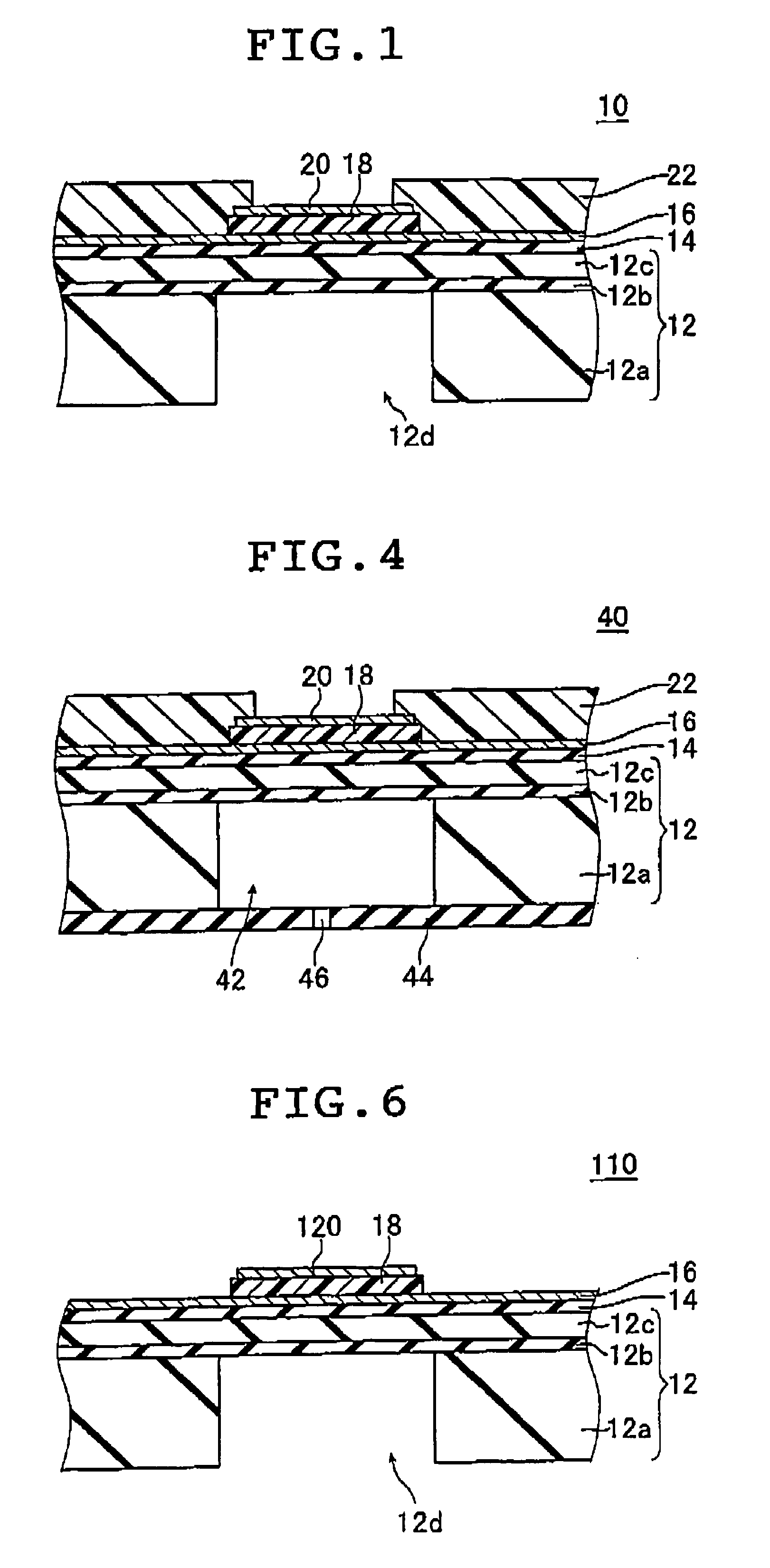
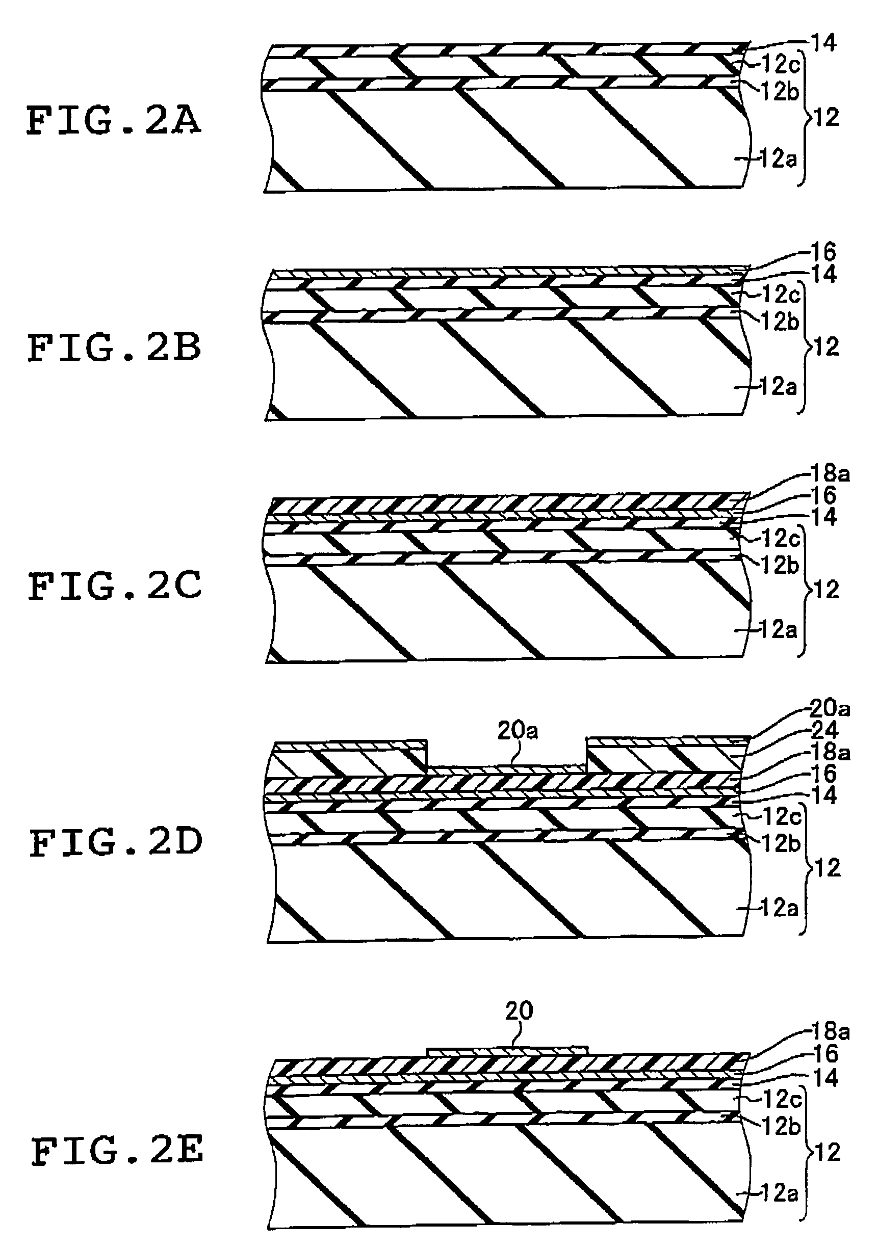
[0022]According to the present invention, a second electrode having a water vapor transmission rate of not more than 1 g / m2 / day is deposited on the piezoelectric film and, in addition, at least one protective layer is deposited to cover at least the peripheries of the second electrode and the piezoelectric film, the protective film having an opening in a position that corresponds to the piezoelectric film except its periphery; as a result, the ingress of moisture from the lateral sides of the second electrode and the piezoelectric film into the piezoelectric film can be prevented to provide a piezoelectric device having satisfactory moisture resistance, as well as a liquid-ejecting head including this piezoelectric device. In particular, there can be provided a highly functional piezoelectric device having satisfactory moisture resistance that has a piezoelectric film as deposited by vapor phase deposition such as sputtering to have high piezoelectric constant and which yet is capable of effectively preventing the ingress of moisture into the piezoelectric film, as well as a liquid-ejecting head that includes this piezoelectric device.

Problems solved by technology

Piezoelectric actuators that utilize piezoelectric films having high piezoelectric constant that have been deposited by vapor phase deposition such as sputtering are particularly sensitive to the above-described problems due to water, i.e., the occurrence of leakage current, dielectric breakdown in the piezoelectric film due to the leakage current, and deterioration of the piezoelectric film due to the reaction the constituent elements in the piezoelectric film undergo with water.
This eventually promotes the deterioration of the piezoelectric film.
Since such dense protective films have high Young's modulus and residual stress, they inhibit the action of the actuator, causing the problem of considerably reducing its performance, as by preventing it from producing the amount of displacement or force it inherently has the ability to produce.
This design, however, requires adjustment in the alignment between the sealing substrate and the channel-forming substrate, thus presenting the problems of complicating the manufacturing process and increasing the manufacturing costs.
In addition, the piezoelectric element holding section and the sealing substrate that are provided to seal the piezoelectric element add to the overall thickness, which in turn increases the overall size of the liquid-propelling head.

Method used


Image

  • Piezoelectric device and liquid-ejecting head
  • Piezoelectric device and liquid-ejecting head
  • Piezoelectric device and liquid-ejecting head

Examples


example 1

[0086]A piezoelectric actuator of the type indicated by 10 in FIG. 1 was fabricated by the production process depicted in FIGS. 2A to 3E. The thus fabricated piezoelectric actuator 10 was subjected to a durability test for evaluating its moisture resistance. The results of the durability test are shown in FIG. 5.

[0087]The piezoelectric actuator 10 as the test sample had the upper electrode 20 composed of a 10-nm thick Ti layer (adhesive layer) and a 200-nm thick Ir layer (electrically conductive layer). The upper electrode 20 including the 200-nm thick Ir layer had a water vapor transmission rate of 0.1 g / m2 / day. Thus, the test sample satisfied the requirement of the present invention that the water vapor transmission rate of the upper electrode should be not more than 1 g / m2 / day. The piezoelectric actuator under test also had a 500-nm thick SiN film as a protective film.

[0088]The piezoelectric actuator of Example 1 was placed in a humid atmosphere (80% RH) at 40° C. while a voltage...


PUM


Abstract

The piezoelectric device includes a substrate, a first electrode deposited on the substrate, a piezoelectric film deposited on top of at least a part of the first electrode by vapor phase deposition, a second electrode deposited on the piezoelectric film and having a water vapor transmission rate of not more than 1 g / m2 / day, and at least one protective film that covers at least peripheries of the second electrode and the piezoelectric film and which has an opening in a position corresponding to the piezoelectric film except the periphery thereof. The piezoelectric device has satisfactory moisture resistance and is capable of effectively preventing the ingress of moisture into the piezoelectric film.

Description

[0001]The entire contents of documents cited in this specification are incorporated herein by reference.BACKGROUND OF THE INVENTION[0002]The present invention relates to a piezoelectric device having a piezoelectric film deposited by vapor phase deposition, and a liquid-ejecting head that utilizes the piezoelectric device.[0003]In recent years, active R&D efforts are being directed to various kinds of devices that use the piezoelectric element, as exemplified by actuators, sensors and memory devices, and piezoelectric films that are deposited by vapor phase deposition such as sputtering are drawing particular attention as functional films capable of high performance. Such piezoelectric films are typically used in the actuator section of inkjet heads, micropumps and so forth.[0004]It is conventionally known that piezoelectric films in an applied electric field are vulnerable to high temperature and humidity and that they (the piezoelectric element) will deteriorate upon exposure to t...

Claims


Application Information

Patent Timeline
Patent Type & Authority Patents(United States)
IPC IPC(8): H01L41/047B41J2/045B41J2/055B41J2/135B41J2/14B41J2/16H01L41/09H01L41/18H01L41/22H01L41/23H01L41/29H01L41/316H01L41/39
CPCB41J2/14233B41J2/161B41J2/1628B41J2/1631H01L41/0973B41J2/1646H01L41/1876H01L41/316B41J2/1642B41J2002/1425H10N30/2047H10N30/8554H10N30/076
Inventor HISHINUMA, YOSHIKAZUMOCHIZUKI, FUMIHIKO
Owner FUJIFILM CORP
Why Eureka
Try Eureka