Method and system of communications for high data rate transmission

a high data rate and communication method technology, applied in the field of high data rate communication, can solve the problem that the radio link solution does not offer sufficient aggregate user data data ra

Active Publication Date: 2011-05-24
TELEFON AB LM ERICSSON (PUBL)
View PDF5 Cites 23 Cited by
  • Summary
  • Abstract
  • Description
  • Claims
  • Application Information

AI Technical Summary

Benefits of technology

[0021]It is consequently an object of the present invention to achieve an antenna configuration for line of sight communication useful for providing low error rates at moderate transmission power within limits as may be required by due authorities.
[0025]Finally, it is an object to relieve the dependency on tangible interconnections, such as wire lines or optical fibers, for interconnection of base stations or other nodes of a telecommunications system. Such interconnections are generally associated with great initial investment costs and maintenance costs.

Problems solved by technology

Present radio link solutions do not offer sufficient data rates of aggregate user data, as to / from a base station, including a plurality of high rate user data links at reasonable power levels for reasonably sized element antenna apertures.

Method used


Image

  • Method and system of communications for high data rate transmission
  • Method and system of communications for high data rate transmission
  • Method and system of communications for high data rate transmission

Examples


Embodiment Construction

[0046]In backbone networks based on wireless communications it is important to achieve capacity to handle data rates of aggregate traffic, where individual peak user data rates are in the order of 100 Mbps to 1 Gbps.

[0047]Fixed fiber optical networks are not always applicable. They are often associated with great costs, provide little or no flexibility and occupy extensive ground space.

[0048]Prior art Multiple Input Multiple Output, MIMO, communications systems most commonly are designed to utilize scattering and, therefore, requires a scattering environment.

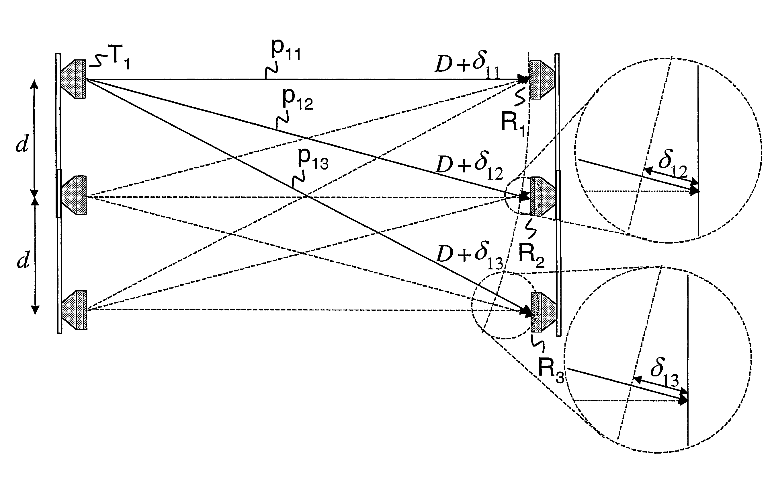
[0049]The present invention is not dependent on such scatterers and suits line of sight communication very well. A theoretical reason for this is its exploitation of spherical wave fronts and associated phase differences.

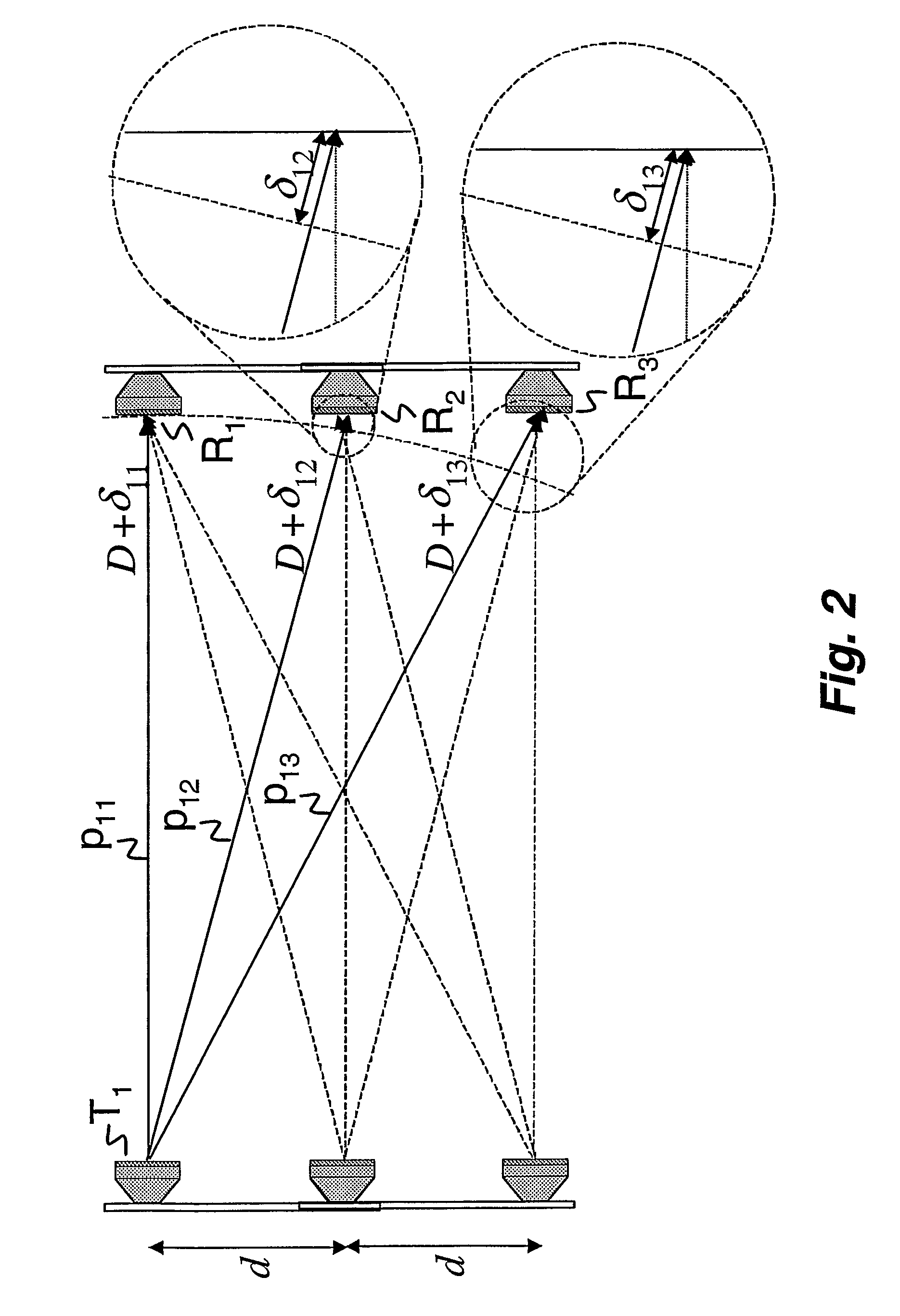
[0050]FIG. 2 schematically illustrates propagation paths and principles of the invention. Respective propagation paths 11>>, 12>>, 13>> between a transmitter antenna > and receiver antennas 1>>, 2>>, 3>> differ ...


PUM


Abstract

In a method and system for configuring an antenna for line of sight (LOS) communication procedures are implemented for providing low error rates at moderate transmission power. The antenna is configured for a particular communications distance over line of sight links providing multiple-input multiple-output communication links, including radio links and optical wireless communications links.

Description

TECHNICAL FIELD OF THE INVENTION[0001]The present invention relates to high data rate communications, and more especially it relates to line of sight, LOS, multiple input multiple output, MIMO, links, such as radio links and optical wireless communications links. For reasons of simplicity elements receiving or emitting electromagnetic fields are referred to as antenna elements as, e.g., light emitters and sensors are direct correspondences in light communications to antenna elements for radio wave communications.BACKGROUND AND DESCRIPTION OF RELATED ART[0002]High-speed wireline or fiber optic connections of backbone networks interconnecting nodes of a terrestrial radio access network are previously known. It is also known to interconnect radio base stations with microwave links providing interconnections of moderate data rates.[0003]Increased antenna area of prior art microwave link antennas increases signal quality, but also increases irradiated microwave power as does transmission...

Claims


Application Information

Patent Timeline
Patent Type & Authority Patents(United States)
IPC IPC(8): H01Q21/00H01Q1/24H01Q19/10H01Q19/28H01Q21/06H01Q21/22H01Q21/28H01Q25/00H04B7/024H04B7/0413H04Q7/30H04Q7/36
CPCH01Q1/246H01Q19/104H01Q19/28H01Q21/061H04B7/04H01Q21/22H01Q21/28H01Q25/00H04B7/02H01Q21/065H04B7/024H04B7/0413
Inventor SIGNELL, SVANTELARSSON, PETER
Owner TELEFON AB LM ERICSSON (PUBL)
Why Eureka
Try Eureka