Machine tool control system

a control system and machine tool technology, applied in the direction of electric controllers, program control, instruments, etc., can solve the problems of complex programs for inputting information and commands, inability to access all of the devices on the machine tool, and inability to use prior art systems for such information and commands. to achieve the effect of reducing the complexity of programming required

Inactive Publication Date: 2011-05-24
FIVES LANDIS
View PDF43 Cites 44 Cited by
  • Summary
  • Abstract
  • Description
  • Claims
  • Application Information

AI Technical Summary

Benefits of technology

[0005]Bearing in mind the problems and deficiencies of the prior art, it is therefore an object of the present invention to provide a machine tool control system that reduces the complexity of programming required for inputting information and commands.

Problems solved by technology

Prior art systems for input of such information and commands have not been easy to use.
Problems have included the complexity of programs for inputting information and commands, the inability to access all of the devices on the machine tool, the lack of flexibility of pre-programmed cycles of commands, and the inability to use such systems on a variety of different machine tools.

Method used


Image

  • Machine tool control system
  • Machine tool control system
  • Machine tool control system

Examples


Embodiment Construction

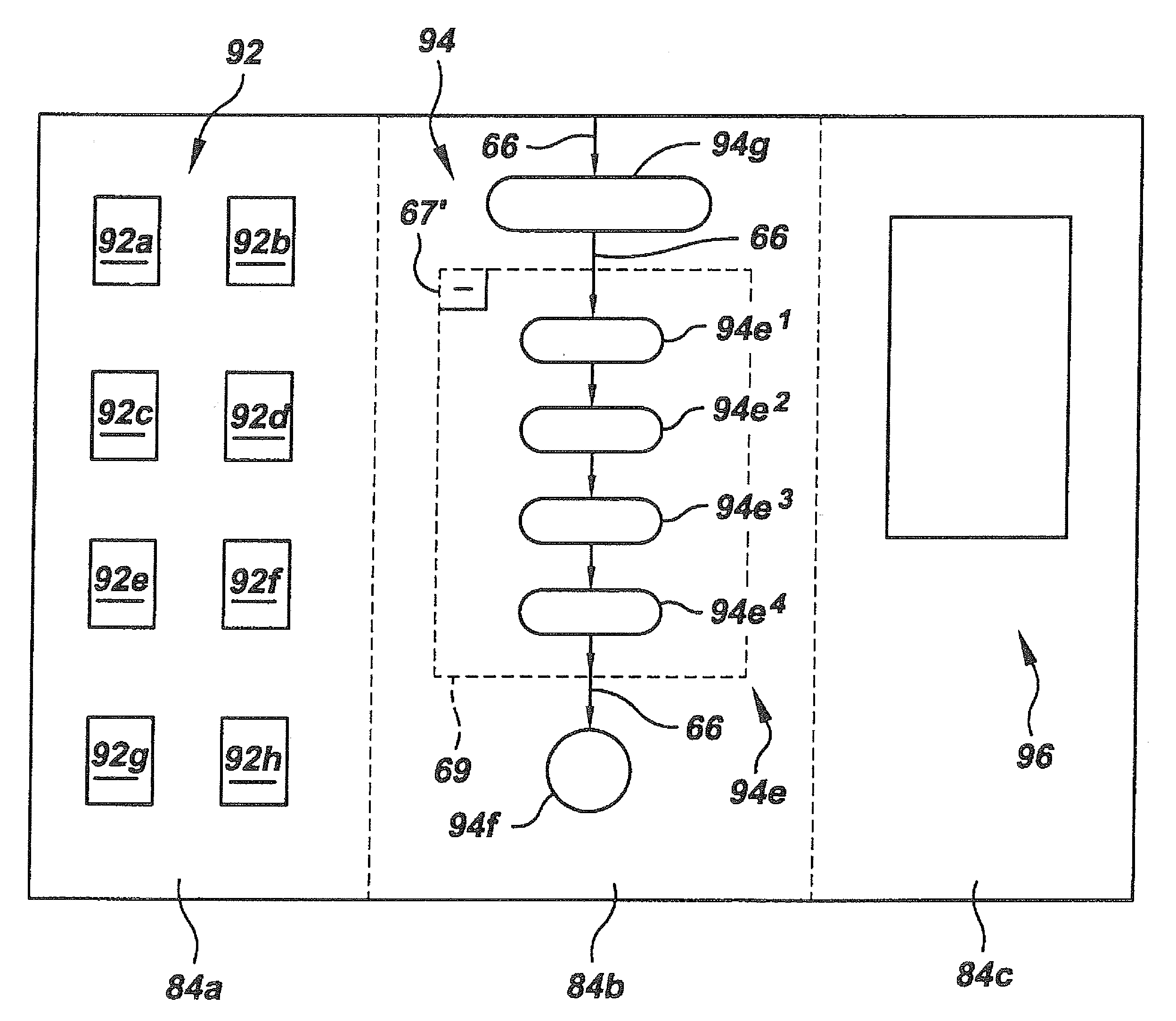
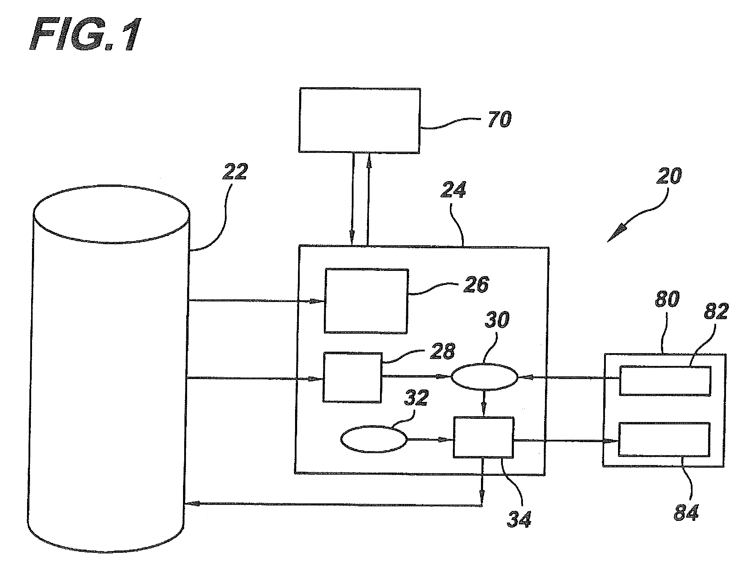
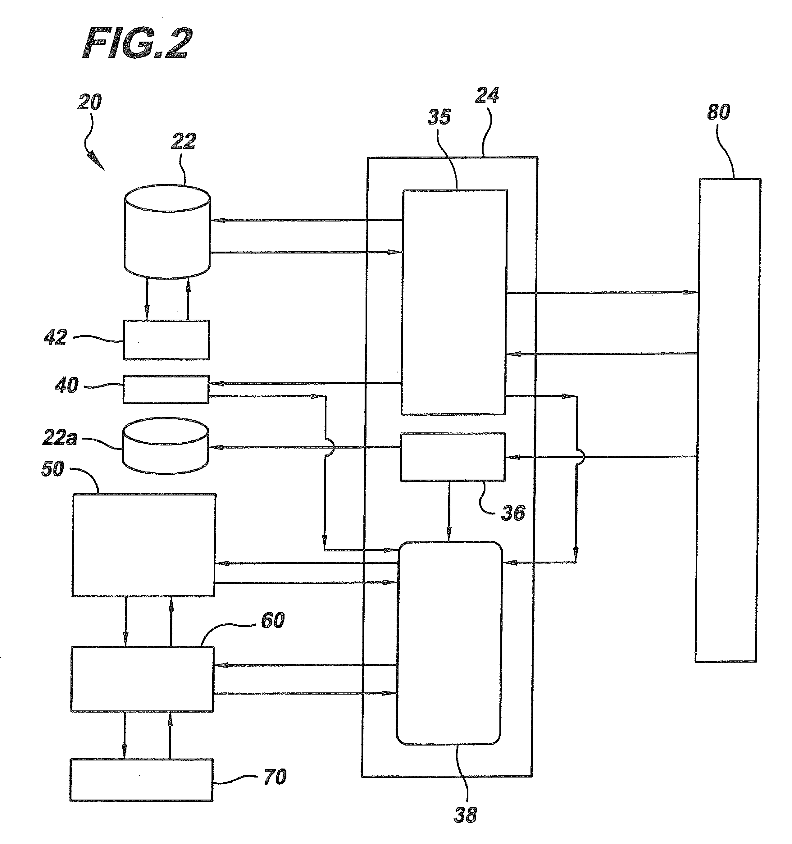
[0032]In describing the preferred embodiment of the machine tool control system of the present invention, reference will be made herein to FIGS. 1-13 of the drawings in which like numerals refer to like features of the invention. As shown in FIG. 1, the machine tool control system 20 includes an operator interface or control 80 with an operator user terminal 80 having an input device 82 and a visual display device 84 having a programmer screen, and a hard drive data storage device 22. Storage device 22 may comprise any device for storing electronic data (including computer programs), such as a semiconductor chip, a read-only memory, magnetic media such as a diskette or computer hard drive, or optical media such as a CD or DVD ROM. The storage device may be local to the operator interface 80 or may be available over a network. Operator interface control 24 includes a microprocessor for executing programs and other operations described below, as well as any required memory for program...


PUM


Abstract

A machine tool control system. A machine tool controller is provided to receive commands from an input source and provide control instructions to a machine tool based at least in part on the commands. An operator interface is provided for inputting commands to the controller. The interface includes a display screen having images of individual command functions, the images being selectable on the screen to place into a sequence of command functions selected by an operator. A sequence generator indicates sequential ordering of the command functions represented by the sequence of images on the screen, such that a sequence of images on the screen selected by the operator is translated by the operator controller sequence generator into a sequence of commands to be inputted into the controller. The operator interface may include one or more images each representing a plurality of individual command functions in a defined sequence.

Description

BACKGROUND OF THE INVENTION[0001]1. Field of the Invention[0002]The present invention relates to a control system and method of controlling a machine tool.[0003]2. Description of Related Art[0004]Computer numerically controlled (CNC) or other programmable machine tools have long been know to machine parts based on programmed inputs. Such machine tools generally employ grinding or cutting tools, and include grinders, lathes, broaches, drills, milling machines and the like. The operators of the machine tools are required to input the specific information and commands that a machine tool is to execute to make a part. Prior art systems for input of such information and commands have not been easy to use. Problems have included the complexity of programs for inputting information and commands, the inability to access all of the devices on the machine tool, the lack of flexibility of pre-programmed cycles of commands, and the inability to use such systems on a variety of different machine...

Claims


Application Information

Patent Timeline
Patent Type & Authority Patents(United States)
IPC IPC(8): G06F19/00G06F9/44
CPCG05B19/056G05B19/409
Inventor LITTLE, ROBBY J.RAMEN, JEFFREY P.LAUZON, DAVID W.CARON, PHILIP H.DESBIENS, RICHARD L.
Owner FIVES LANDIS
Why Eureka
Try Eureka