Heat dissipation module

a heat dissipation module and heat dissipation module technology, applied in lighting and heating apparatus, cooling/ventilation/heating modification, semiconductor devices, etc., can solve problems such as incomplete soldering, concave upward portion, and create clearances, so as to speed up the joint, prevent abnormal phenomena, and create clearance and excessive solder

Inactive Publication Date: 2011-05-31
ASIA VITAL COMPONENTS SHENZHEN CO LTD
View PDF7 Cites 2 Cited by
  • Summary
  • Abstract
  • Description
  • Claims
  • Application Information

AI Technical Summary

Benefits of technology

[0012]In order to overcome the deficiencies of the preceding prior art, an object of the present invention is to provide a heat dissipation module which comprises a cooling base, at least a guide heat pipe and a cooling fin set; the cooling base provides at least a circular recess and at least a receiving groove; the guide heat pipe is placed in the circular recess; the cooling fin set is joined to the cooling base and provides a lower folding side at each cooling fin thereof and the folding side has at least a concave upward portion corresponding to the circular recess; and the receiving groove is disposed at two end sides of the circular recess for receiving solder, soldering paste, solder club or bonding agent. Therefore, when the cooling fin set and the guide heat pipe are joined to the cooling base, the receiving groove is capable of speeding up the joint and preventing abnormal phenomena such as incomplete soldering, creating clearance and excessive solder.

Problems solved by technology

Besides, another type of the cooling fin set does not provide the concave upward portion at the folding side such that a joining seat is equipped to have a circular upward recess for covering the guide heat pipe.
However, there are following deficiencies while the preceding conventional radiators are fabricated.
Because the cooling base has a flat top, it is easy to result in problems such as incomplete soldering, creating clearances, undesirable locating and excessive solder at the soldering spots.
The problems leads to low guide heat efficiency between the cooling base A1 and the cooling fin set A3.

Method used


Image

  • Heat dissipation module
  • Heat dissipation module
  • Heat dissipation module

Examples


Embodiment Construction

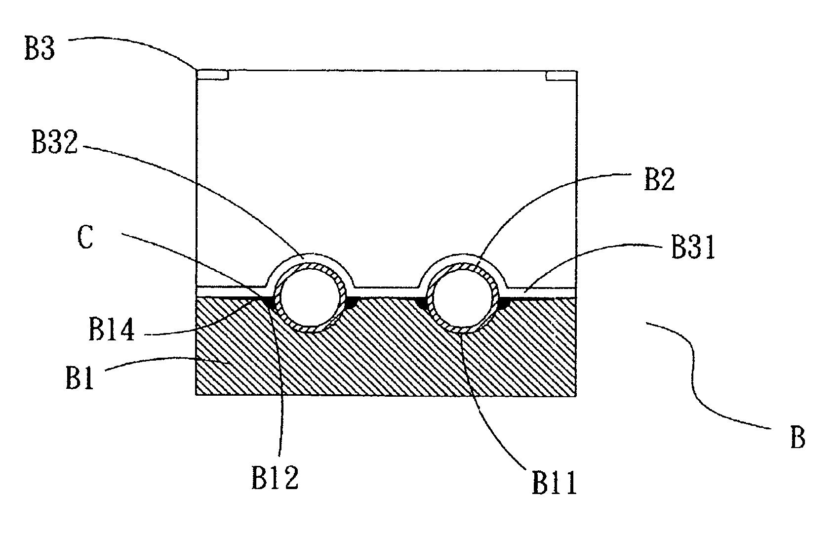
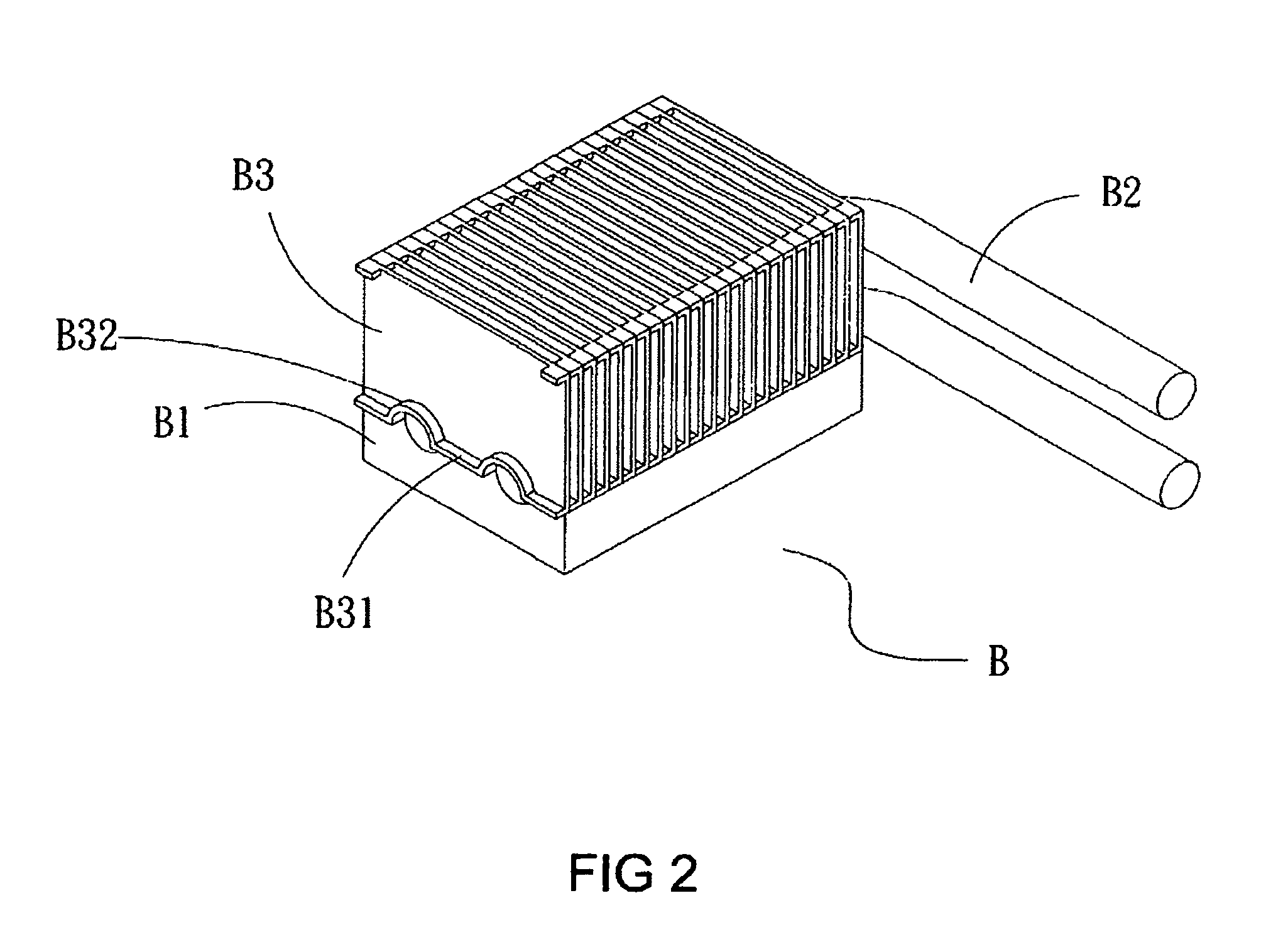
[0022]Referring to FIGS. 2 to 4, a heat dissipation module B according to the first preferred embodiment of the present invention includes a cooling base B1, two heat pipes B2 and a cooling fin set B3. Wherein, the cooling base B1 provides at least an elongated circular recess B11 and at least a receiving groove B12 extending along two elongated end sides of the circular recess B11. A slant surface B14 is provided on the cooling base B1 next to the respective end side of the circular recess B11. Each cooling fin of the cooling fin set B3 has a lower folding side B31 and the lower folding side has at least a concave upward portion B32.

[0023]When the preceding parts are assembled, the receiving groove B12 is filled with solder, solder club or soldering paste and the heat pipe B2 is placed in the recess B11. Then the cooling fin set B3 is placed on the heat pipe B2 and the cooling base B1 in a way of the concave upward portion B32 contacting with the heat pipe B2 and an inclining clear...


PUM


Abstract

A heat dissipation module includes a cooling base, at least a guide heat pipe and a cooling fin set. The cooling base provides at least a circular recess and at least a receiving groove. The guide heat pipe is placed in the circular recess. The cooling fin set is joined to the cooling base and provides a lower folding side at each cooling fin thereof and the folding side has at least a concave upward portion corresponding to the circular recess. The receiving groove is disposed at two end sides of the circular recess for receiving solder, soldering paste, solder club or bonding agent. Therefore, when the cooling fin set and the guide heat pipe are joined to the cooling base, the receiving groove is capable of speeding up the joint and preventing abnormal phenomena such as incomplete soldering, creating clearance and excessive solder.

Description

BACKGROUND OF THE INVENTION[0001]1. Field of the Invention[0002]The present invention is related to a heat dissipation module and particularly to a heat dissipation structure, which is capable of being fabricated speedily and joining the cooling fin set, the guide heat pipe and cooling base together tightly.[0003]2. Brief Description of the Related Art[0004]The integrated circuit provides a size getting smaller along with progress of semiconductor technology. In order to allow the integrated circuit being able to treat more data, multiple times of components can be received in an integrated circuit with the same size than before. More and more components being provided in the integrated circuit, more and more heat is generated. Taking the central processing unit (CPU) as an example, the heat generated by the CPU is sufficient to burn out the CPU itself in case of the full work load being performed. Hence, the heat dissipation device for the CPU is an important subject worth us to ca...

Claims


Application Information

Patent Timeline
Patent Type & Authority Patents(United States)
IPC IPC(8): F28F7/00H05K7/20
CPCF28D15/0275H01L23/427H01L23/467H01L23/3672H01L2924/0002H01L2924/00
Inventor SHEN, CHING-HANG
Owner ASIA VITAL COMPONENTS SHENZHEN CO LTD
Why Eureka
Try Eureka