
Apparatus and method for dispensing machine control

a technology of apparatus and vending machine, which is applied in the direction of instruments, apparatus for dispensing discrete objects, and registering coins as credit, etc., can solve the problems of increasing labour costs, major maintenance costs, and increasing labor costs, and achieves the effect of limiting the use of the machine and facilitating quality control

Inactive Publication Date: 2011-05-31
TUTTOESPRESSO SRL
View PDF11 Cites 13 Cited by
  • Summary
  • Abstract
  • Description
  • Claims
  • Application Information

AI Technical Summary

Benefits of technology

[0034]It is a further object of the present invention to provide an apparatus, easy to assemble and relatively not expensive, wherein the status and the operating conditions of the dispensing machine can be detected in an easy and quick way.
[0043]Also quality control is made easier, because the electronic tags store identification codes, readable only by the controller, which guarantee the full compatibility of a module or tray or component with the machine's desired specifications (e.g. voltage etc.).
[0044]Another advantage is that it is possible to limit the use of the machine with unauthorized modules or components, including food product containers, and with modules the life-span of which has expired and that could be dangerous if used (e.g. a boiler, a water filter etc.).

Problems solved by technology

Known dispensing machines have several drawbacks that derive mainly from being subject to heavy use and located in many different places, different conditions of use and different maintenance routines.
Maintenance is a major problem.
Such a maintenance is extremely expensive even in the modular dispensing machines and the increasing labour cost is forcing service companies in charge of such maintenance to become extremely accurate in the use of their time.
Another problem of these known machines is their quality control, both at the production stage and when maintenance is carried out.
Inserting the wrong module could result in damaging the machine or in a bad beverage being dispensed.
A still further problem derives from the fact that traditional dispensing machines do not allow for inhibiting the activation of specific modules.
Such memorizing operations are long, complex and source of possible errors.

Method used


Image

  • Apparatus and method for dispensing machine control
  • Apparatus and method for dispensing machine control
  • Apparatus and method for dispensing machine control

Examples


Embodiment Construction

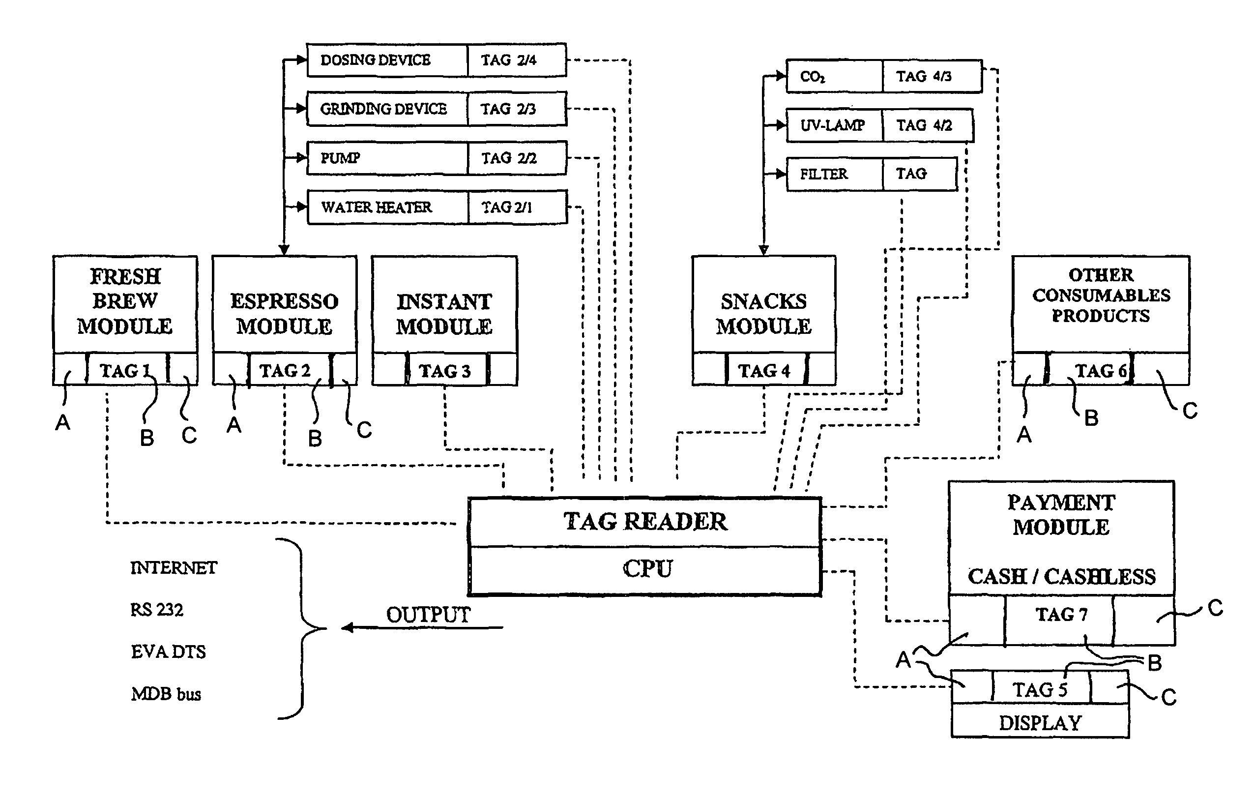
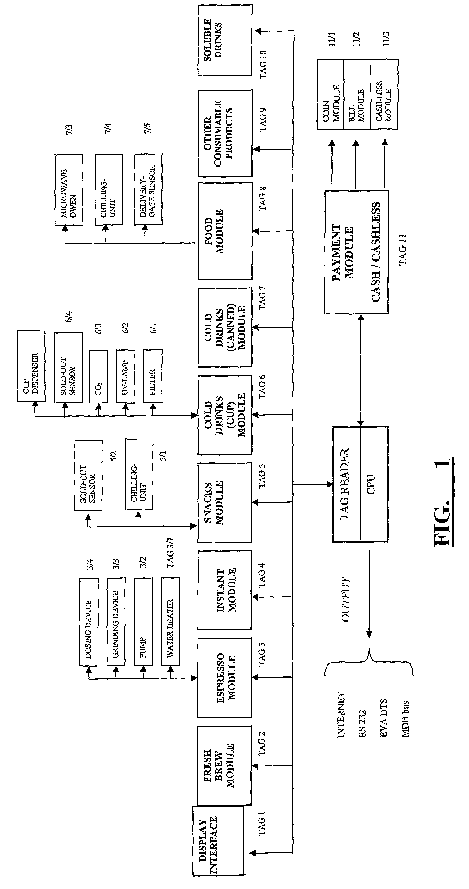
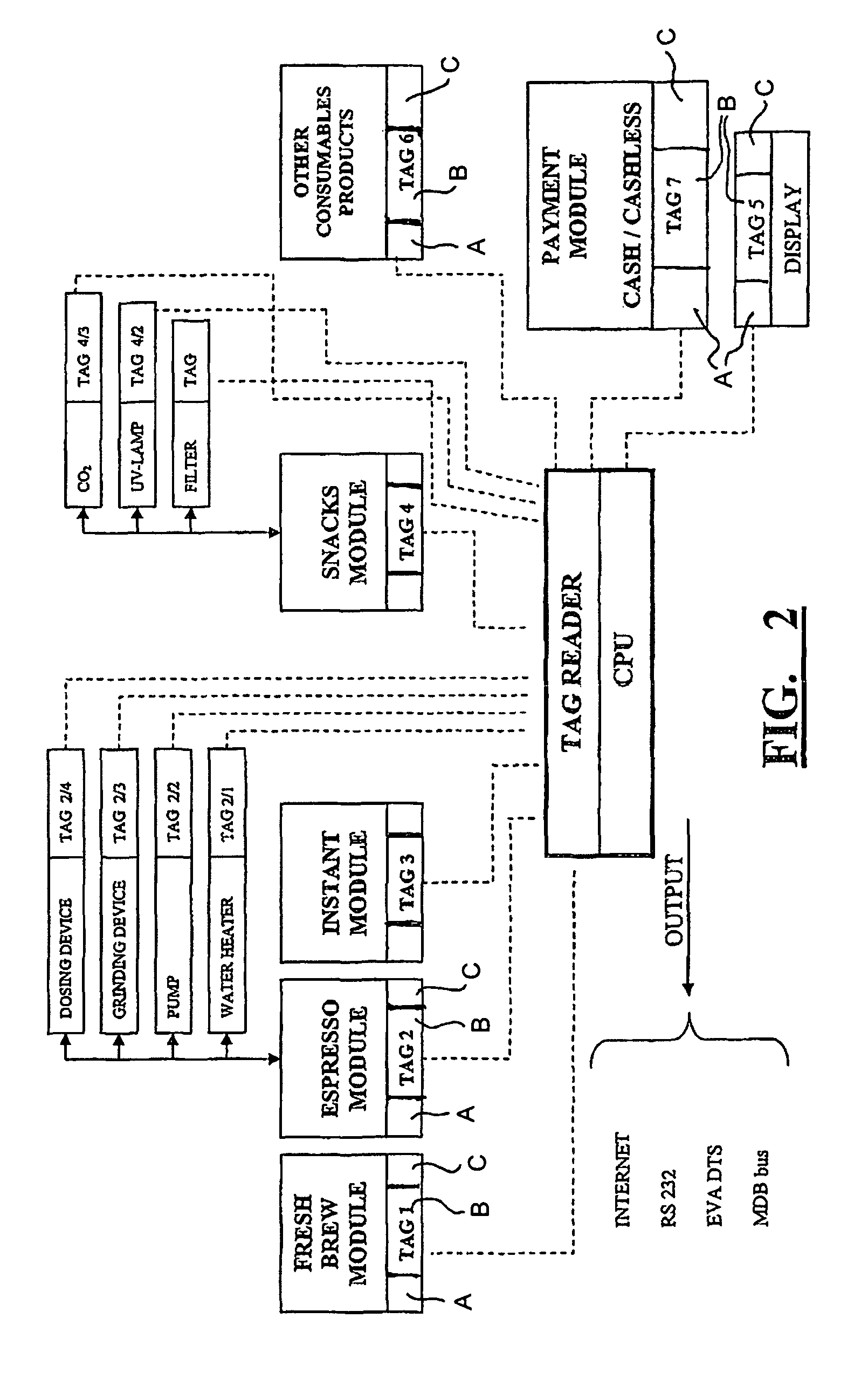
[0054]FIG. 1 refers to a dispensing machine provided with several modules, sub-modules and components. In particular FIG. 1 is a scheme which shows the internal logic layout of a dispensing machine for dispensing snacks, foodstuff, cold drinks, espresso coffee, etc., each product being prepared and dispensed by the related module. The sub-assemblies are indicative of one possible configuration for some modules without restricting the amount of sub-modules or modules and combinations thereof that can comprise one specific dispensing system.

[0055]Modules may comprise several sub-modules or components. For example, the module “ESPRESSO” will comprise a power unit, a dosing device, a pump, a boiler, a grinder or similar devices. Similarly, the module “COLD DRINKS” will comprise sub-module for processing cold drinks including a filter, a UV lamp, a CO2 (carbonating unit) sub-module and a sold-out sensor. In FIG. 1 each module and each sub-module or component is provided with a tag; tags ...


PUM


Abstract

In order to control the status and the operation of a dispensing machine assembly comprising one or more modules or sub-assemblies, at least one of modules or sub-modules is provided with an electronic tag and the machine is provided with a tag controller device for interacting with said tag by reading, writing and transmitting information data on or through said tag and operating said dispensing machine according to the information gathered from said tag or tags.

Description

[0001]This is a continuation of serial no. PCT / IB2005 / 002300 filed Aug. 3, 2005.FIELD OF THE INVENTION[0002]The present invention relates to an apparatus and a method for controlling dispensing and vending machines. More particularly, the invention relates to an electronic-tag based apparatus and method for controlling an electrically operated dispensing machine.BACKGROUND OF THE INVENTION[0003]In the present application the wording “dispensing machines” generally refers to both so-called “vending” and “dispensing” machines, i.e. to machines including a means of payment of the dispensed product (vending machines), and machines without a means of payment of the dispensed product (dispensing machines). Exemplary vending machines are those for selling to the public newspapers, flowers, CDs, drinks, snacks and similar products; exemplary dispensing machines are machines for dispensing hot and cold beverages, foodstuff, etc. as can be found e.g. in hotel lobbies or airport lounges or eve...

Claims


Application Information

Patent Timeline
Patent Type & Authority Patents(United States)
IPC IPC(8): G06F7/08
CPCG07F5/18G07F11/002G07F9/026G07F9/002G07F9/001G06F3/122G07F5/22G07G1/0045
Inventor MAJER, DOGLIONI
Owner TUTTOESPRESSO SRL
Learn More