Gas-liquid mixing device

a mixing device and gas liquid technology, applied in the direction of gas purification by liquid washing, gas purification by non-gaseous materials condensation, fuel gas production, etc., can solve the problems of unexpected stoppage of vacuum cleaners, and achieve the effect of improving the efficiency of gas-cleaning installations and optimizing the efficiency of mixing

Inactive Publication Date: 2011-05-31
WINDDROP
View PDF12 Cites 10 Cited by
  • Summary
  • Abstract
  • Description
  • Claims
  • Application Information

AI Technical Summary

Benefits of technology

[0019]This invention is aimed at optimizing the efficiency of the mixing between a gas loaded with debris and a liquid, in order to improve the efficiency of a gas-cleaning installation, namely a vacuum cleaner, namely with liquid filtering, while providing a safety mechanism that avoids the liquid of the tank from leaving towards the gas suction and the motor when said tank is full.
[0029]the venturi effect used and the various variant designs of the mixing device allow an excellent liquid-gas mixing with formation of fine droplets, a significant stirring and thus a good efficiency in separating the debris contained in the gas flow to be cleaned.
[0031]the device has a reduced size and authorizes high gas flow-rates, which is favorable for the construction of a small-size gas-cleaning installation and an important efficiency.
[0032]various configurations are possible for enhancing the liquid-gas mixing and in the same device can be performed the liquid-gas separation, which is absolutely necessary before evacuating to the outside the gas from the gas-cleaning installation, which is then very compact.

Problems solved by technology

The main technical difficulties met in developing the vacuum cleaners with water filtering is due to the fact that, in a first step, a very intimate mixing must be performed between the air loaded with debris and the water of the vacuum cleaner, then, when said debris are trapped in the water, an as effective as possible separation of the water must be performed, before the passing through the suction module and before the rejection into the atmosphere of the room, in order to remove the droplets in suspension from the gas flow.
This device has however the drawback of reacting too quickly in an air flow with a high flow-rate, which causes unexpected stoppages of the vacuum cleaner.

Method used


Image

  • Gas-liquid mixing device
  • Gas-liquid mixing device
  • Gas-liquid mixing device

Examples


Embodiment Construction

[0038]The invention relates to the field of the cleaning treatment of gases, namely air, in industrial or household applications.

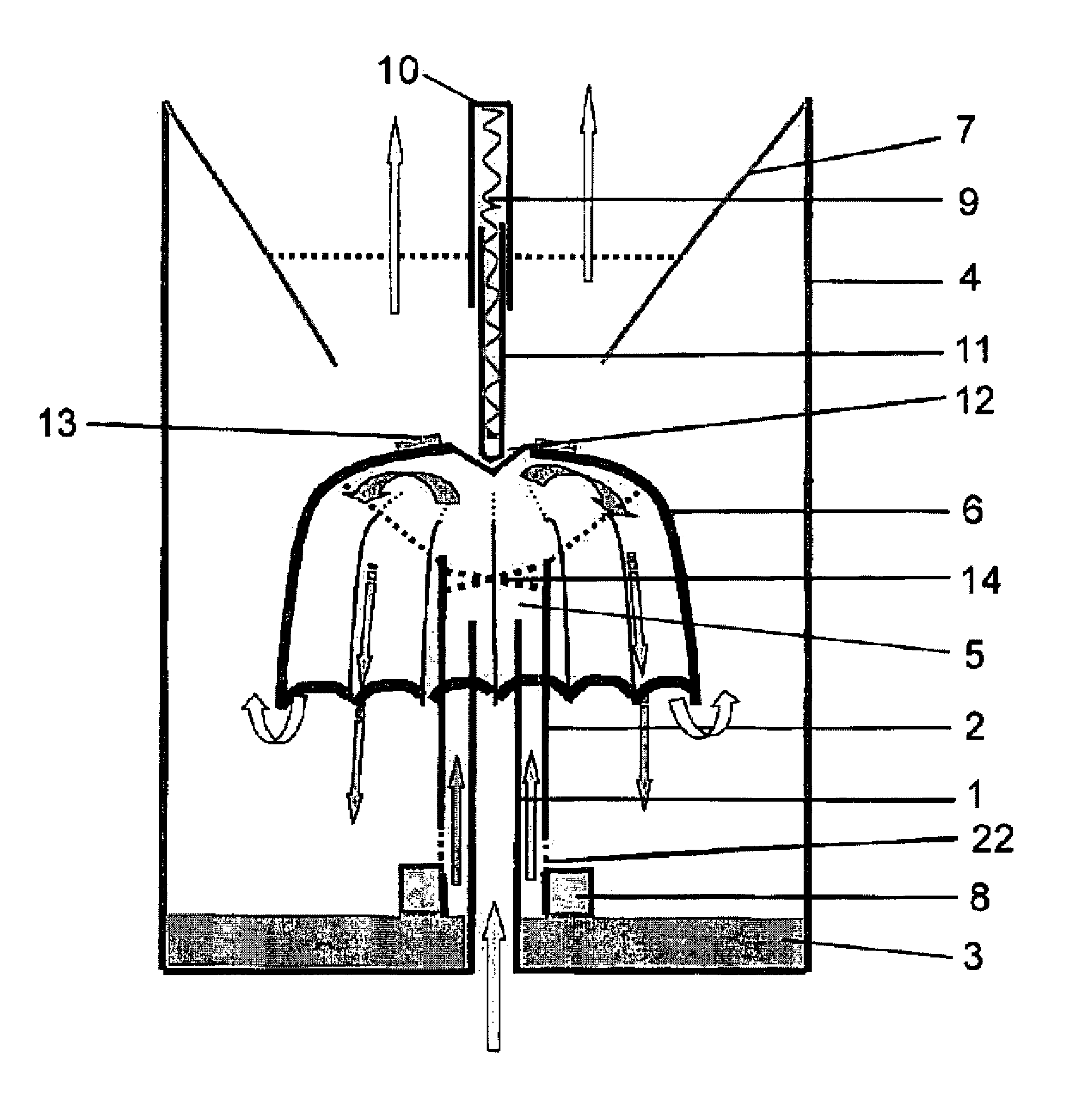
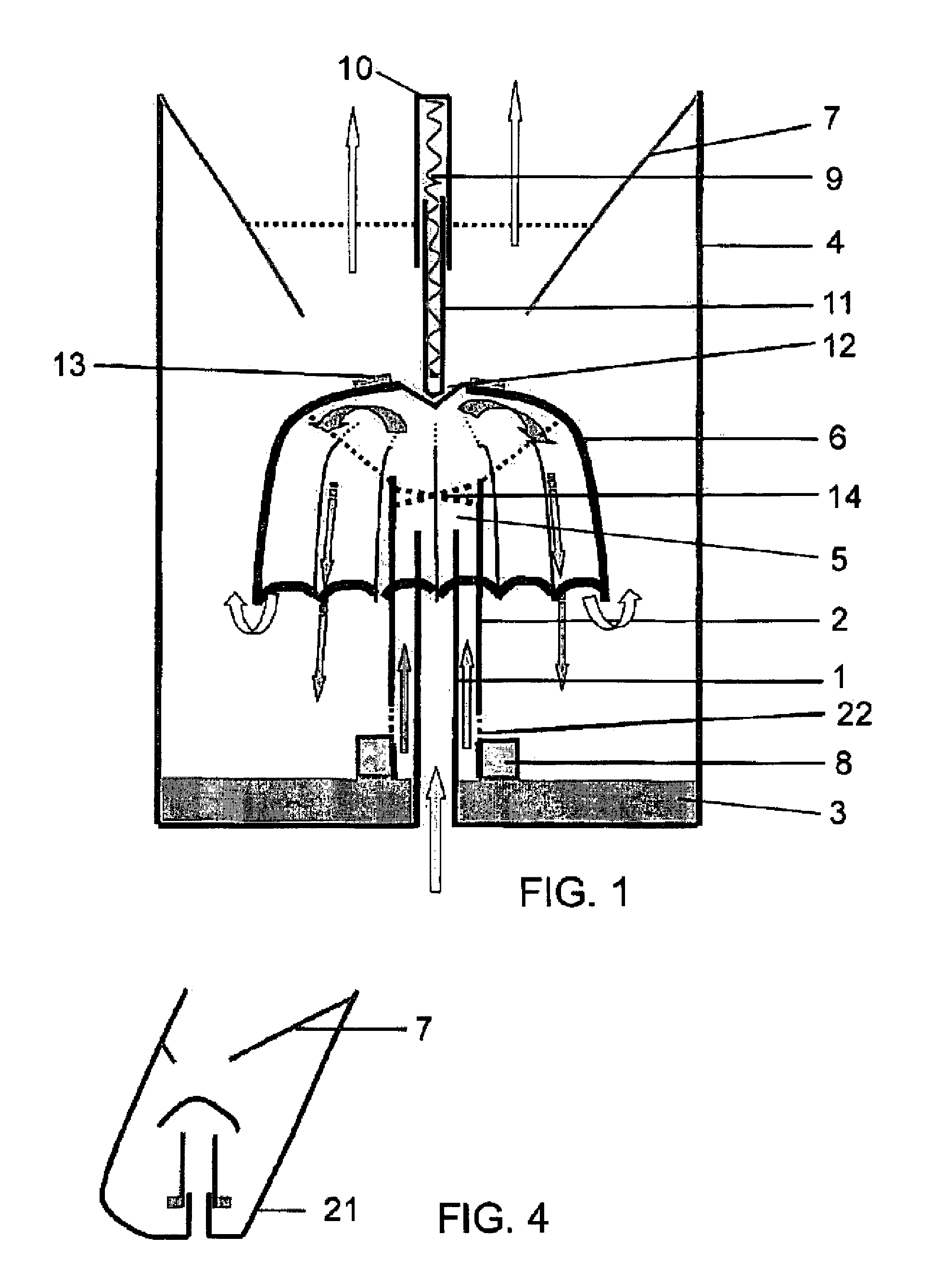
[0039]A first variant of a gas-liquid mixing device forming a safety valve according to the invention is shown in FIG. 1.

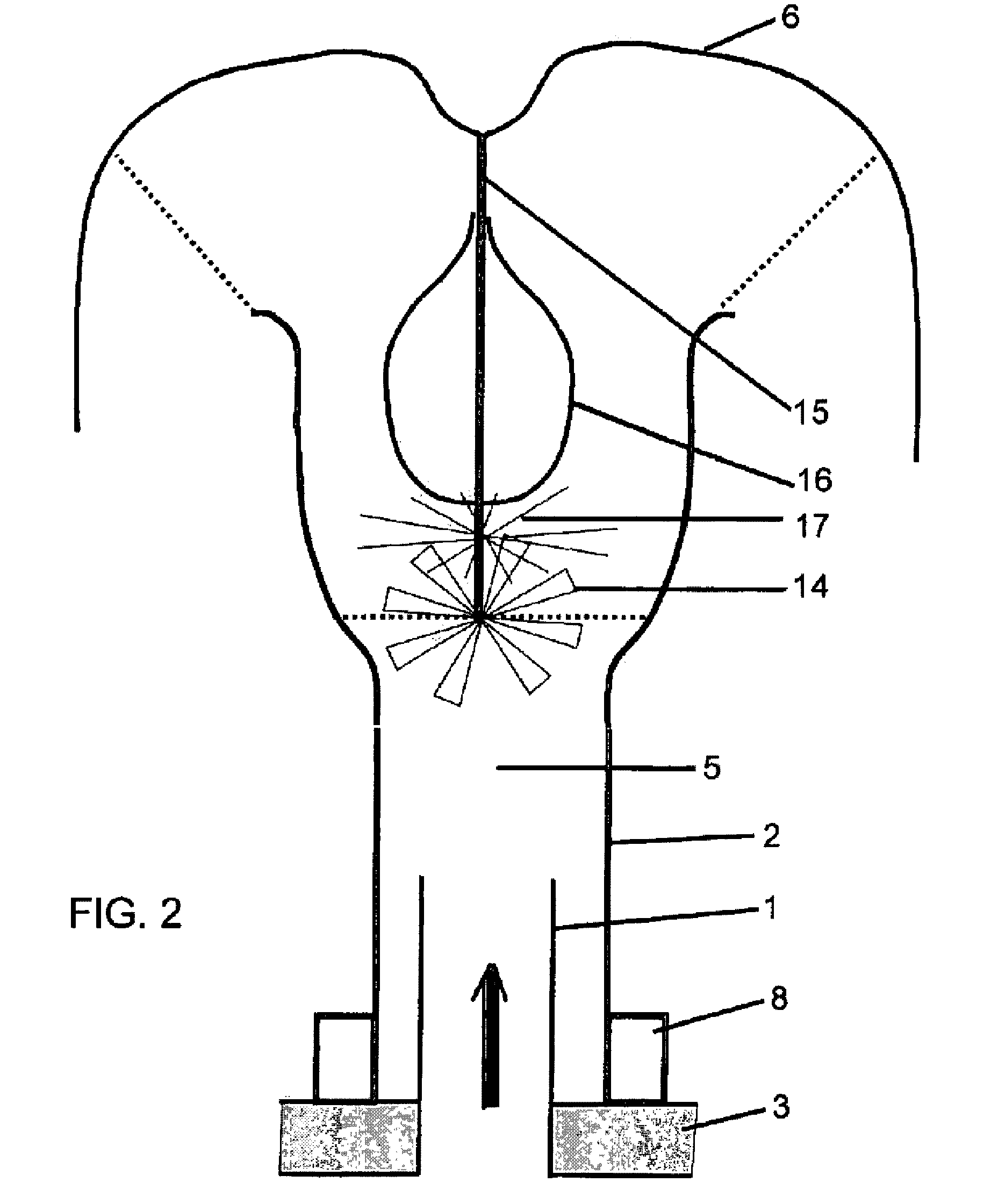
[0040]The gas-liquid mixer operates according to the principle of the venturi effect.

[0041]A gas flow proceeding from an inlet conduit of a gas-cleaning installation, for example a vacuum cleaner with water filtering at the level of a suction nozzle, arrives in the direction of the arrow at an inlet 1, which has preferably a tubular form. This gas flow generates a negative pressure and a suction in an external tube 2 concentric to the inlet 1; since the tube 2 is into direct contact with the liquid 3 contained in a tank 4, in its lower portion, there occurs a suction of liquid and its ejection in the direction of the gas flow in a pressure-relief zone 5. This tube 2 is sliding around the inlet 1.

[0042]A gas-cleaning installation, namely ...


PUM

PropertyMeasurementUnit
sizeaaaaaaaaaa
pressureaaaaaaaaaa
weightaaaaaaaaaa

Abstract

This invention relates to a gas-liquid mixing device, forming a safety valve, designed capable of being incorporated into a gas-cleaning installation including a liquid tank (4), an inlet (1) for gas to be cleaned and an outlet (7) through which the gas flow is evacuated. It is characterized in that it has:a tube (2) sliding around the gas inlet (1) and including a peripheral float (8) located in its lower end and designed capable of floating in said tank (4), said sliding tube (2) being open in its lower portion, in order to draw liquid from said tank (4) by a venturi effect and to create a mist in a pressure-relief zone (5);a mixing chamber (6) interposed between said sliding tube (2) and said outlet (7), and designed capable of conveying the flow of said mist towards the bottom of said tank (4).

Description

BACKGROUND OF THE INVENTION[0001](1) Field of the Invention[0002]The invention relates to a gas-liquid mixing device, forming a safety valve, designed capable of being incorporated into a gas-cleaning installation including a liquid tank, an inlet for the gas to be cleaned and an outlet through which the gas flow is evacuated.[0003]It also relates to a gas-cleaning installation provided with such a gas-liquid mixing device.[0004]It also relates, in particular, to a vacuum cleaner with water filtering provided with such a gas-liquid mixing device.[0005]The invention relates to the field of the cleaning treatment of gases, in particular air, in industrial or household applications.[0006]Among the latter, the traditional vacuum cleaners with water filtering include a suction device which drives an air flow loaded with debris through a tank containing water. The filtering of the impurities occurs in this water through bubbling, then the air is evacuated towards the outside after passing...

Claims


Application Information

Patent Timeline
Patent Type & Authority Patents(United States)
IPC IPC(8): B01F3/04
CPCA47L9/183B01D47/16B01D47/06A47L9/185
Inventor CURIEN, GERARD
Owner WINDDROP
Why Eureka
Try Eureka