Vibration isolator system

a technology of vibration isolator and isolator plate, which is applied in the direction of shock absorbers, machine supports, other domestic objects, etc., can solve the problems of difficult or impossible to achieve the geometric relationships prescribed by the schemes disclosed in gran and denice in many real world situations, and achieve the effect of preventing vibration of a suppor

Active Publication Date: 2011-05-31
DRS NETWORK & IMAGING SYST
View PDF18 Cites 27 Cited by
  • Summary
  • Abstract
  • Description
  • Claims
  • Application Information

AI Technical Summary

Benefits of technology

[0011]The present inventors have recognized that vibration of a support may be prevented from inducing angular rotation of a payload by satisfying geometric constraints substantially less restrictive than those disclosed in the prior art. For example, in accordance with various embodiments of the present invention, a projected elastic center may be caused to coincide with a supported object's center of mass even though the lines of action of isolators do not intersect at the supported object's center of mass. Neither is it required that parallel struts be disposed in pairs.
[0012]In accordance with systems and apparatuses consistent with the present invention, a vibration isolator system for attaching a payload to a supporting base is provided, the payload having a center of mass and the system consisting of at least three vibration isolating pods. Each pod has two associated, non-parallel, elastic struts. A first end of each strut is attached to the supporting base and a second end of each strut is attached to the payload at a respective mounting point, and the a projected elastic center of the system is substantially co-located with said center of mass. The vibration isolator system is operable to substantially prevent translational vibration of the supporting base from inducing angular rotation of the payload.

Problems solved by technology

A problem exists for many system configurations where it is impossible to provide elastic struts having attachment points to the payload in a common plane containing the payload's cm.
The geometric relationships prescribed by the schemes disclosed in Gran and Denice are difficult or impossible to achieve in many real world situations.

Method used


Image

  • Vibration isolator system
  • Vibration isolator system
  • Vibration isolator system

Examples


Embodiment Construction

[0026]Reference will now be made in detail to an implementation in accordance with methods, systems, and products consistent with the present invention as illustrated in the accompanying drawings.

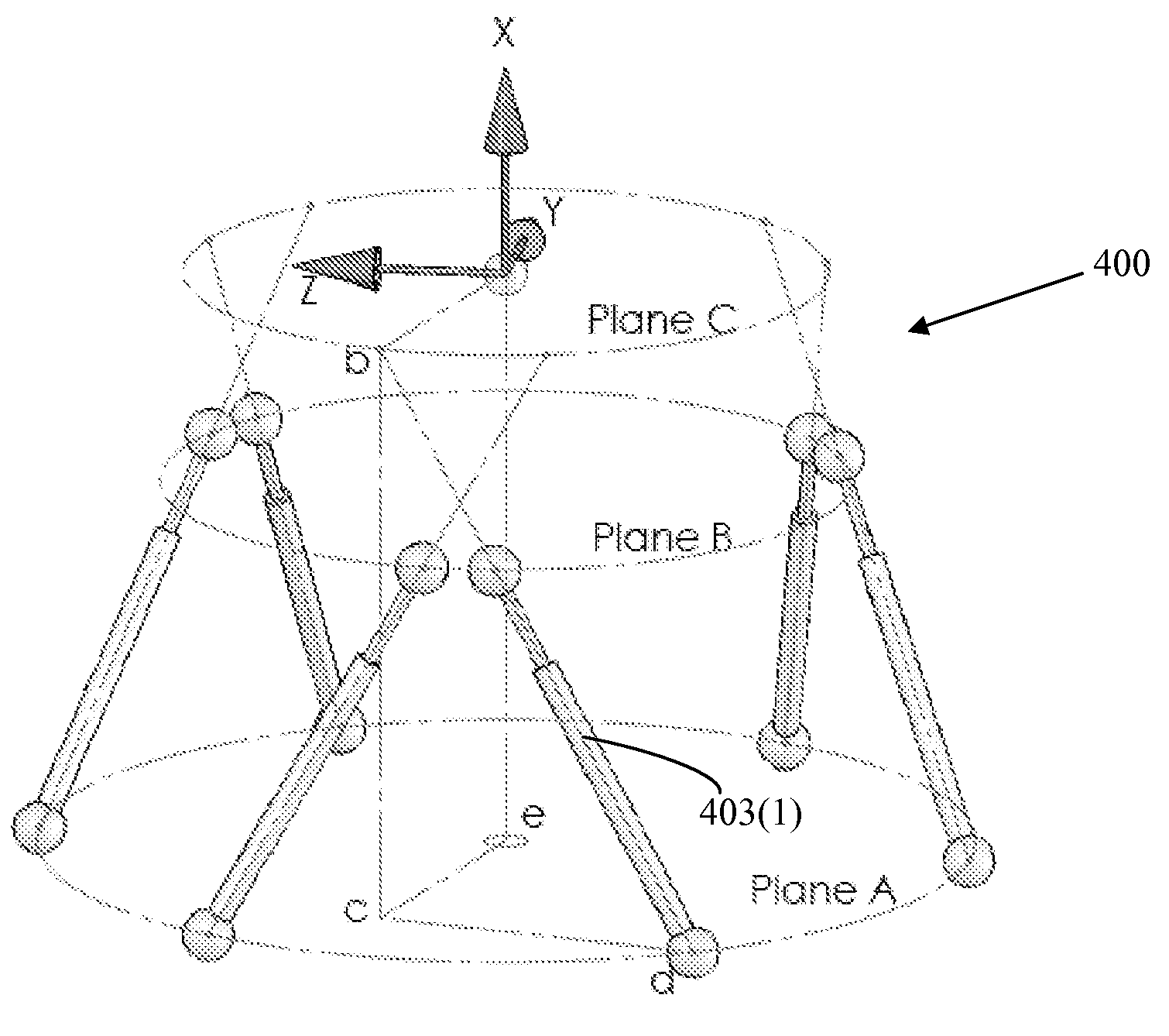
[0027]In an embodiment, a supported structure, for example a payload, is attached to a supporting base, for example a vehicle chassis, or other supporting structure, by at least three vibration isolating pods. Each pod may consist of two associated, non-parallel, elastic struts. Advantageously, the pods are arranged in such a manner that a projected elastic center is substantially co-located with said center of mass.

[0028]As the term is used herein, an elastic strut (or “strut”) may be any type of elastic member having a line of action along a corresponding longitudinal axis. For example, a strut may consist of a simple spring element, or a spring element with a damper element, working together as a shock absorber. In order to provide for substantially linear motion along the longitudinal a...


PUM


Abstract

A vibration isolator system for attaching a payload to a supporting base is provided, the payload having a center of mass and the system consisting of at least three vibration isolating pods. Each pod has two associated, non-parallel, elastic struts. A first end of each strut is attached to the supporting base and a second end of each strut is attached to the payload at a respective mounting point, and the a projected elastic center of the system is substantially co-located with said center of mass. The vibration isolator system is operable to substantially prevent translational vibration of the supporting base from inducing angular rotation of the payload.

Description

CROSS REFERENCE TO RELATED APPLICATION[0001]This application claims the benefit of U.S. Provisional Application No. 61 / 086,880, filed Aug. 7, 2008, the content of which is hereby incorporated by reference into the present patent application in its entirety.FIELD OF THE INVENTION[0002]The present invention relates to vibration isolating techniques, particularly techniques for preventing translational vibration of a supporting structure from inducing angular rotation of a payload while minimizing geometric constraints on structures connecting the payload to the supporting structure.BACKGROUND OF THE INVENTION[0003]Vibration isolation is often used to stabilize a payload's angular orientation in the face of translational vibration. The translational vibration may be self induced by the payload (for example by self induced vibration from a motor of a gimbal assembly, or transmitted from a support structure upon which the payload is supported. Rotational motion of a payload may be reduce...

Claims


Application Information

Patent Timeline
Patent Type & Authority Patents(United States)
IPC IPC(8): F16M1/00
CPCF16F15/02F16M11/14F16M11/123F16M11/04
Inventor HILEY, DAVIDCABRERA, REYNALDOBRENNAN, JASON
Owner DRS NETWORK & IMAGING SYST
Why Eureka
Try Eureka