
Shutters for infra red communication at moderate bandwidths

a technology of infra red communication and shutters, applied in the field of freespace communication systems, can solve the problems of high fabrication costs of mqw modulators and slow modulation lc modulators, limited field of view of hollow retroreflectors, and limitations

Inactive Publication Date: 2011-05-31
CUBIC CORP
View PDF7 Cites 8 Cited by
  • Summary
  • Abstract
  • Description
  • Claims
  • Application Information

AI Technical Summary

Benefits of technology

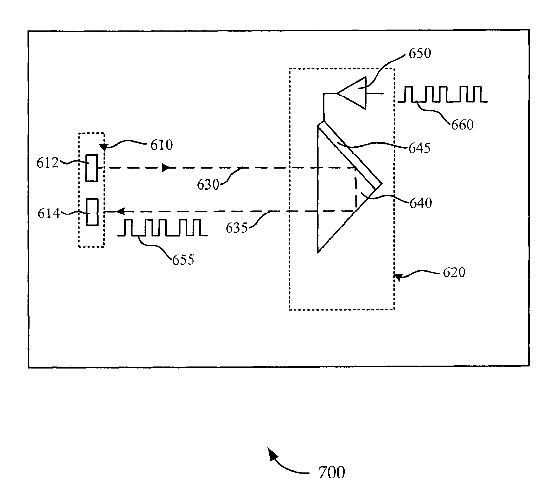
The present patent provides a modulating corner-cube retroreflector for remote communications. The retroreflector includes a thin membrane that can vibrate to modulate information on a reflected beam of light. The retroreflector is designed to receive an incident beam of light and return a reflected beam of light back towards the source. The thin membrane can frustrate total internal reflection of the incident beam of light when positioned at a first distance from the front surface and the three mutually perpendicular surfaces of the retroreflector, and can permit total internal reflection when positioned at a second distance from the front surface and the three mutually perpendicular surfaces of the retroreflector. The technical effect of this invention is to provide a novel and efficient way to modulate information on a reflected beam of light for remote communications.

Problems solved by technology

While such systems have been shown to work, they have their limitations such as high fabrication costs associated with MQW modulators and the slow modulation LC modulators.
While the modulation schemes used with hollow retroreflectors perform quite well the hollow retroreflector has a limited field of view for receiving an incident beam of light.

Method used


Image

  • Shutters for infra red communication at moderate bandwidths
  • Shutters for infra red communication at moderate bandwidths
  • Shutters for infra red communication at moderate bandwidths

Examples


Embodiment Construction

[0024]The ensuing description provides preferred exemplary embodiment(s) only, and is not intended to limit the scope, applicability or configuration of the disclosure. Rather, the ensuing description of the preferred exemplary embodiment(s) will provide those skilled in the art with an enabling description for implementing a preferred exemplary embodiment. It being understood that various changes may be made in the function and arrangement of elements without departing from the spirit and scope as set forth in the appended claims.

[0025]Retroreflectors are optical devices that receive incident light and reflect reflected light back in the same direction as the incident light. Unlike mirrors, which reflect light back toward the source only if the light is incident on the mirror at a right angle to the surface of the mirror, retroreflectors may reflect light back toward a source through a range of incident angles.

[0026]There are many retroreflector designs. The corner-cube retroreflec...


PUM

PropertyMeasurementUnit
critical angleaaaaaaaaaa
incident angleaaaaaaaaaa
critical angleaaaaaaaaaa

Abstract

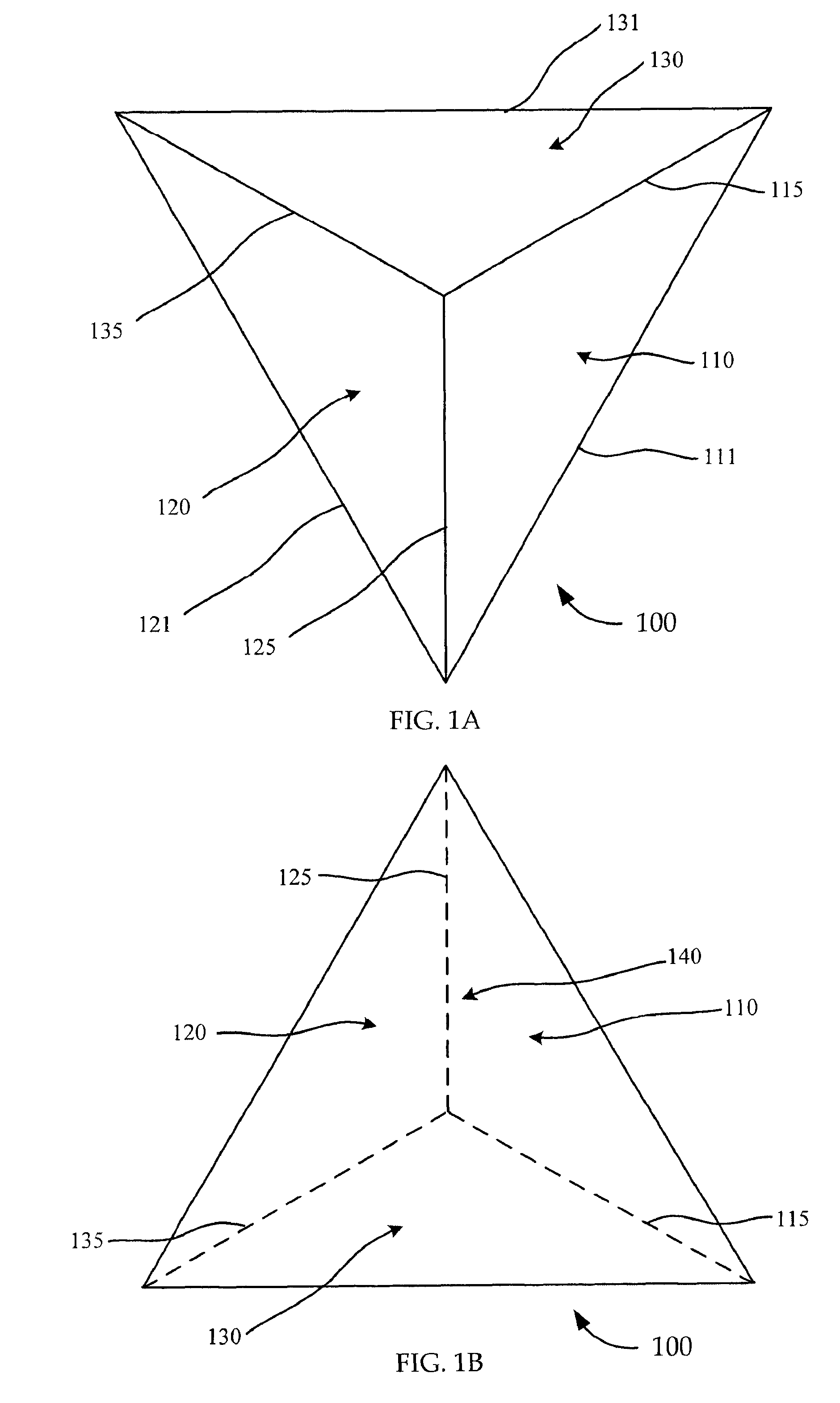
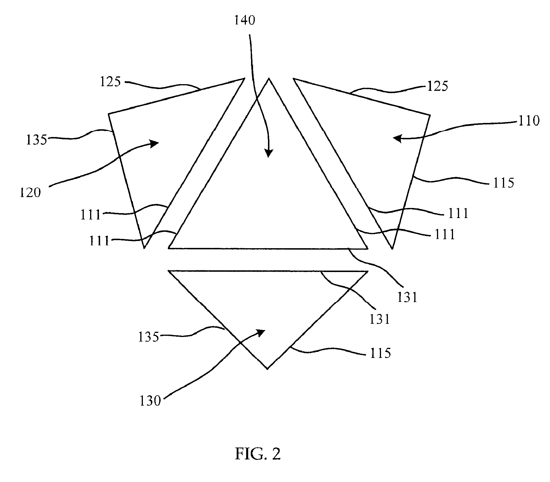
A modulating corner-cube retroreflector for remote communications is disclosed. The modulating corner-cube retroreflector includes a solid retroreflector with a front surface and three mutually perpendicular surfaces: a first surface, a second surface and a third surface. A first thin membrane is disposed relative to at least one of the three mutually perpendicular surfaces and covers at least a portion of the surface. A modulator is included that is adapted to cause the thin membrane to vibrate. The corner-cube retroreflector is configured to receive an incident beam of light from a source along a first path and is configured to return a reflected beam of light back towards the source along a second path that is substantially parallel to the first path. The first thin membrane is configured to substantially frustrate total internal reflection of the incident beam of light when the first thin membrane is moved relative to at least one surface of the retroreflector.

Description

CROSS-REFERENCES TO RELATED APPLICATIONS[0001]This application claims the benefit of and is a non-provisional of co-pending U.S. Provisional Application Ser. No. 60 / 758,014 filed on Jan. 11, 2006, which is hereby expressly incorporated by reference in its entirety for all purposes.BACKGROUND OF THE INVENTION[0002]This disclosure relates in general to free-space communications systems and, but not by way of limitation, to retroreflector modulation of incident light for communication amongst other things.[0003]Modulating retroreflectors provide a self-aligned return signal for a downstream data link in free space optical communications, such as satellite-to-ground, ground-to-satellite, and ground-to-ground transmission of optical data and signals. The optical power demands for the upstream and downstream signal are satisfied at the base station, permitting the remote station to communicate with greatly reduced power demands.[0004]In such communications systems the signal from the remo...

Claims


Application Information

Patent Timeline
Patent Type & Authority Patents(United States)
IPC IPC(8): G02B5/124G02F1/00
CPCG02B5/122G01S17/74G02B26/02
Inventor ROES, JOHN B.TARTAKOVSKY, GENNADY
Owner CUBIC CORP
Learn More