
Heat rejecting optic

a technology of heat sinks and photovoltaic cells, applied in the field of concentrated photovoltaic cells, can solve the problems of insufficient heat sinks, prohibitively expensive concentrations greater than 1000, and severely compromised durability, and achieve the effect of improving solar power production efficiency

Inactive Publication Date: 2013-01-24
AMONIX INC
View PDF8 Cites 4 Cited by
  • Summary
  • Abstract
  • Description
  • Claims
  • Application Information

AI Technical Summary

Benefits of technology

The present invention provides a way to improve the efficiency of solar power production while preserving the photovoltaic cell. This is done by using optical elements that focus desired wavelengths of light onto the cell while rejecting unwanted wavelengths that could cause damage. The optical elements use a principle called total internal reflection (TIR) to concentrate light, with refractive elements and a receiving layer that has a higher refractive index than an intermediate layer. This results in less damage to the cell from the unwanted wavelengths and may even provide benefits such as thermal heating. Overall, the invention enhances solar power production while protecting the photovoltaic cell.

Problems solved by technology

More importantly, durability is severely compromised by unwanted heating as every 10° C. rise in operating temperature cuts photovoltaic cell lifetime in half.
However, in CPV and HCPV systems providing concentrations greater than 1000× heat sinks can be prohibitively expensive and insufficient to prevent thermal damage to the extent needed for optimal performance and cost competitiveness of solar power systems.
Unfortunately, these filters are expensive and degrade with time such that the theoretically intuitive solution is less than desirable as applied in practice.

Method used


Image

  • Heat rejecting optic
  • Heat rejecting optic
  • Heat rejecting optic

Examples


Embodiment Construction

Definitions

[0017]As used herein, the following terms are defined as indicated below, consistent with the principle that a patentee can be his own lexicographer.

[0018]“Intermediate layer” refers to a thin (sub-wavelength) layer having a lower refractive index positioned between an optical element and receiving element or layer having higher refractive indices than it. The intermediate layer may be, but is not limited to, an air gap or magnesium fluoride (MgF2). In cases in which the intermediate layer is a material composition it may be coated on the receiving element or layer or optical element, including through dipping, spray deposition, or other methods.

[0019]“Receiving element or layer” refers to a medium having a higher refractive index than the intermediate layer and separated from an optical element by the intermediate layer into which the evanescent wave of undesired wavelengths coupled out of the optical element is received. The receiving element or layer may take any one o...


PUM


Abstract

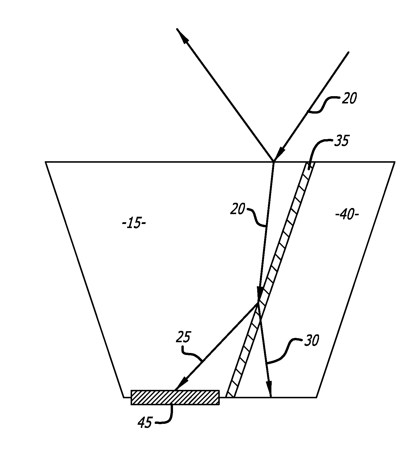
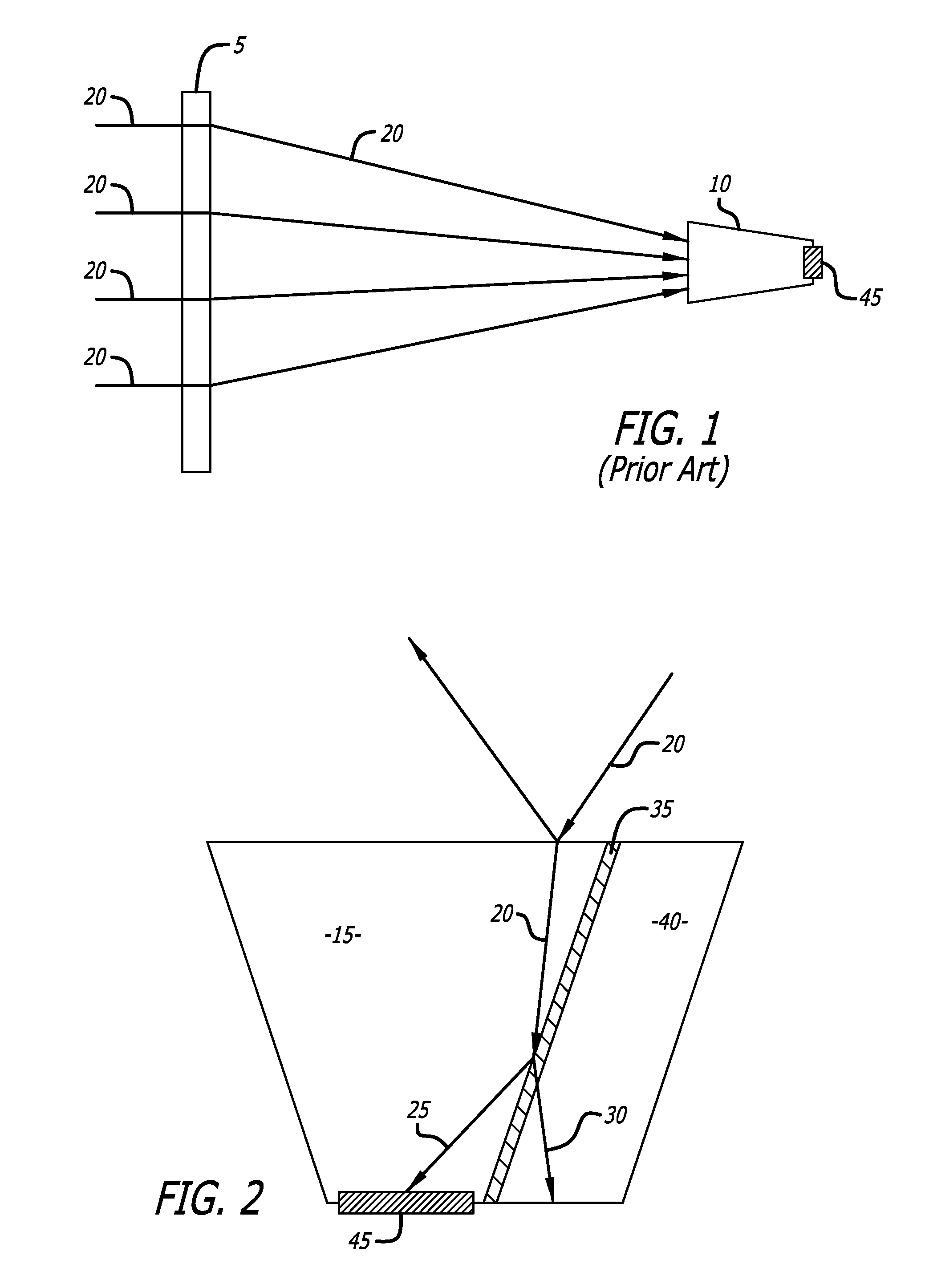
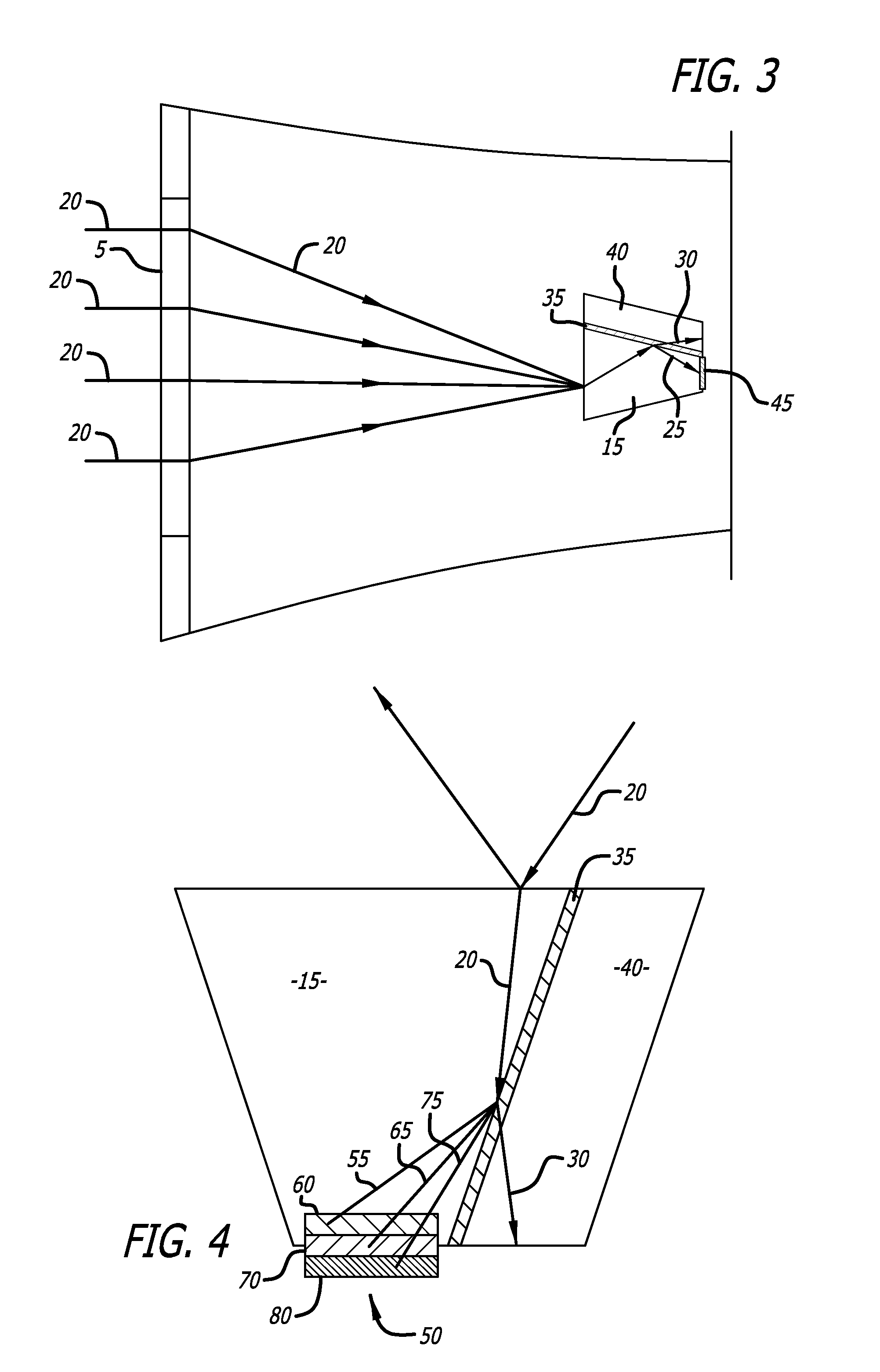
A heat-rejecting optic comprising an optical element and receiving element or layer with intermediate layer between is provided. Refractive indices of the optical element and receiving element or layer are greater than the intermediate layer. The optic may be part of a concentrator assembly or lens concentrator system for photovoltaic cells. The heat-rejecting optic functions to redirect wavelengths of light for which power conversion by a photovoltaic cell is inefficient and which cause undesirable photovoltaic cell heating and damage, reducing photovoltaic cell life. The receiving element or layer and intermediate layer modify the optical element to frustrate the total internal reflection of light that would otherwise occur within the optical element and divert that light into the receiving element or layer.

Description

BACKGROUND[0001]1. Field of the Invention[0002]The present invention relates to concentrators for photovoltaic cells that reduce thermal damage to photovoltaic cells by deflecting some wavelengths of radiation for which the efficiency of power production is outweighed by heating damage to the photovoltaic cell. The present invention also relates to methods of reducing thermal damage to solar arrays and methods of manufacturing solar power modular assemblies to enhance power conversion efficiency and improve durability.[0003]2. Description of the Related Art[0004]Preventing thermal damage to photovoltaic cells is especially a concern with concentrated photovoltaic (CPV) and highly concentrated photovoltaic (HCPV) multijunction photovoltaic cells. Heat rejection is critical for operation and durability of a CPV or HCPV system. Power production decreases by more than 1% for every 10° C. temperature increase. More importantly, durability is severely compromised by unwanted heating as ev...

Claims


Application Information

Patent Timeline
Patent Type & Authority Applications(United States)
IPC IPC(8): H01L31/0232H01L31/06B05D1/18G02B27/56B05D5/06B05D1/36H01L31/024G02B5/28
CPCG02B5/208G02B27/126Y02E10/52H01L31/18H01L31/0549H01L31/02325H01L31/0524H01L31/0543G02B27/1006
Inventor NAYAK, ADITYAKINSEY, GEOFFREY S.
Owner AMONIX INC
Learn More