Fingerprint and palmprint image collector with honeycomb structure, and terminal device

a terminal device and fingerprint and palmprint technology, applied in the field of image acquisition, can solve the problems of difficulty in reducing the thickness of the optical fingerprint acquisition apparatus, the difficulty of the existing image scanner to meet the requirements of various electronic terminals, etc., and achieve the effect of convenient use, improved shielding, and compact structur

Active Publication Date: 2019-11-19
VKANSEE (BEIJING) TECHNOLOGY CO LTD
View PDF21 Cites 3 Cited by
  • Summary
  • Abstract
  • Description
  • Claims
  • Application Information

AI Technical Summary

Benefits of technology

[0006]An object of the disclosure is to provide a fingerprint and palmprint image collector with a honeycomb structure and a terminal device, which has the compact structure, thin thickness and low cost, and can improve the contrast of the fingerprint image and the adaptive capacity for dry and wet fingers.
[0017]After employing the above solution, the present disclosure has the following advantages.
[0018]1. The fingerprint and palmprint image collector with the honeycomb structure, which is composed of a light guide plate, a honeycomb plate, a light source and an image sensor, has a compact structure and a thinner thickness. When a finger or a palm touches the light guide plate, the total internal reflection of light in the light guide plate is frustrated. Part of the light is projected on a surface of the finger or palm leaking from the light guide plate, to form light diffused in various angles. With the vias which are parallel to each other and densely disposed on the honeycomb plate, it is ensured that only the light in a single direction parallel to the vias can pass through the honeycomb plate, and thus stray light in multiple directions can be better shielded. The sizes of the vias are set to allow only a single light or light beam to enter the vias, and the imaging is performed only in a smaller range, such as one pixel, such that the size of an acquired fingerprint and palmprint is equal to the size of an acquired image. The light parallel to or approximately parallel to the vias is projected on the image sensor through the vias to generate an digital image signal. For the acquisition of the fingerprint or palmprint, parallel light is used to facilitate acquisition of a high-contrast image based on the valley structure of the finger or palm. That is, for parallel light in a single direction which is reflected after the finger or palm touches the light guide plate, the intensity of light reflected by a ridge of the fingerprint or the palmprint is greater than the intensity of light reflected by a valley of the fingerprint or the palmprint, and thus the image of the fingerprint or palmprint may be clearer.
[0019]2. In this disclosure, a diffuse reflection layer is disposed on a surface of the honeycomb plate close to the light guide plate. Based on such a design, the total internal reflection of light inside the light guide plate is further frustrated, thus the problem of dry finger is effectively solved, and the adaptive capability for the dry and wet fingers is improved.
[0020]3. The fingerprint and palmprint image collector with the honeycomb structure according to the disclosure is integrated into a terminal device, so that the terminal device has a fingerprint and palmprint acquisition function through fewer additional components and lower cost.

Problems solved by technology

In addition, it is difficult for the existing image scanner to meet requirements of various electronic terminals for low cost, small volume and ultra-thinness of the image collector, due to the high cost and complex structure caused by associated components such as the image acquisition prism and the lens.
Therefore, how to reduce the thickness of the optical fingerprint acquisition apparatus becomes a technical problem to be solved.

Method used


Image

  • Fingerprint and palmprint image collector with honeycomb structure, and terminal device
  • Fingerprint and palmprint image collector with honeycomb structure, and terminal device
  • Fingerprint and palmprint image collector with honeycomb structure, and terminal device

Examples


first embodiment

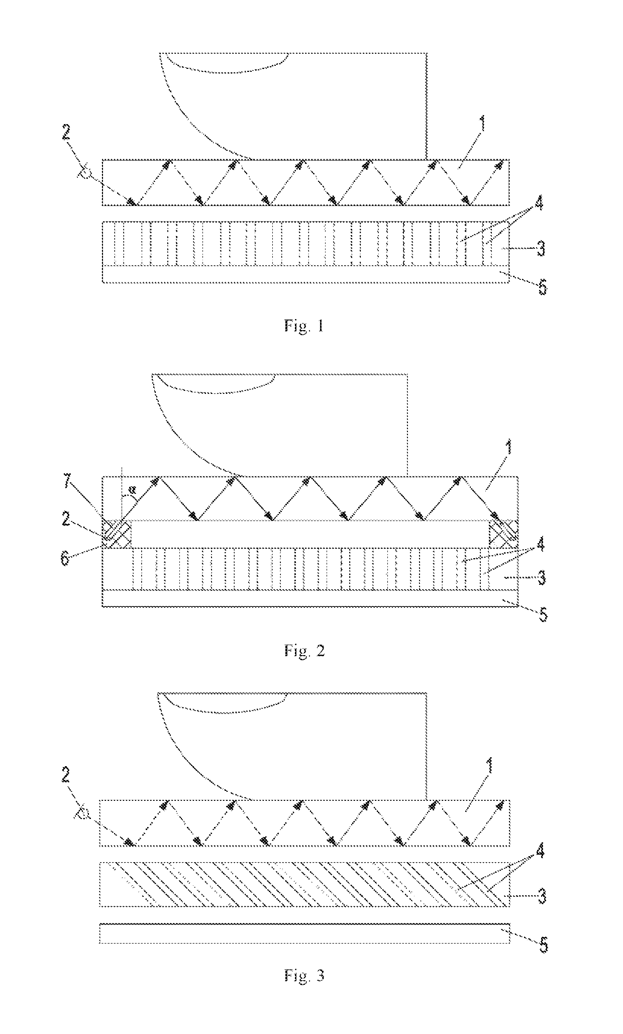
[0031]FIG. 1 shows a schematic diagram of a fingerprint and palmprint image collector with a honeycomb structure according to the present disclosure. The fingerprint and palmprint image collector includes a light guide plate 1, a light source 2, a honeycomb plate 3 and an image sensor 5.

[0032]The light guide plate 1 may be selected from various materials, such as a glass plate and various transparent materials.

[0033]The light source 2 is configured for emitting at least part of light into the light guide plate 1. The light source 2 may be an LED light or other light emitting elements, which is not limited herein. The light source 2 is disposed at a side and / or an upper surface and / or a lower surface of the light guide plate 1. In this embodiment, the light source 2 is disposed at a left side of the light guide plate 1, and directly fixed on the light guide plate 1 in a bonding mode or other fixed modes.

[0034]In this embodiment, the honeycomb plate 3 is disposed below the light sourc...

second embodiment

[0038]FIG. 2 shows a schematic diagram of a fingerprint and palmprint image collector with a honeycomb structure according to the present disclosure, and most of the structure thereof is the same as that in the embodiment shown in FIG. 1. The difference is that, the number of the light sources 2 is two, and the two light sources are fixed on both ends of the lower surface of the light guide plate 1 through supports 6 respectively. A light guide groove 7 is disposed on the upper surface of each of the supports 6. The two light sources 2 are disposed inside two light guide grooves 7 respectively. The light guide grooves 7 are configured to control an angle α between a normal line and light which is emitted into the light guide plate 1 from the light sources 2 through the light guide grooves 7 to be in a range from arcsin(n0 / n2) to arcsin(n1 / n2), where n0 is a refractive index of air, n1 is a refractive index of liquid on a surface of an object contacting the light guide plate 1, and n...

third embodiment

[0039]FIG. 3 shows a schematic diagram of a fingerprint and palmprint image collector with a honeycomb structure according to the present disclosure, and most of the structure thereof is the same as that in the embodiment shown in FIG. 1. The difference is that, the image sensor 5 is disposed below the honeycomb plate 3 and spaced apart from the honeycomb plate 3. The central axis of the via 4 on the honeycomb plate 3 inclines to the lower right. An angle between the central axis of the via and a horizontal plane is greater than or equal to 30 degrees. In this embodiment, the angle is selected to be 45 degrees. The vias 4 are parallel to each other.

[0040]With such a design, when a finger or a palm is touching the light guide plate 1, the total internal reflection of light inside the light guide plate 1 is frustrated. Part of the light is projected onto the surface of the finger or palm leaking from the light guide plate 1 to form light diffused in various angles. Only the light para...


PUM


Abstract

A fingerprint and palmprint image collector with a honeycomb structure and a terminal device are provided. The image collector includes a light guide plate, and a light source for emitting at least part of light into the light guide plate. A surface of the light guide plate is provided with a honeycomb plate. A plurality of vias parallel to each other are densely disposed on the honeycomb plate. The diameter of each via is in a range from 0.5 micrometer to 50 micrometers, and the size of an acquired fingerprint or palmprint is equal to the size of an acquired image. The thickness of the honeycomb plate is more than five times of the diameter of the via. The distance between centers of adjacent vias is less than or equal to 50.8 micrometers. The other surface of the honeycomb plate is provided with an image sensor. The image collector can be integrated into the terminal device. The fingerprint and palmprint image collector with the honeycomb structure according to the invention has a compact structure and a thin thickness, and can improve the contrast of the fingerprint image and the adaptive capacity for dry and wet fingers. The fingerprint and palmprint image collector is integrated into the terminal device so that the terminal device has a fingerprint and palmprint acquisition function through fewer additional component and low cost.

Description

[0001]This application claims the priority to Chinese Patent Application NO. 201510046991.1, titled “FINGERPRINT AND PALMPRINT IMAGE COLLECTOR WITH HONEYCOMB STRUCTURE, AND TERMINAL DEVICE”, filed with the SIPO on Jan. 29, 2015, the entire contents of which are incorporated herein by reference.FIELD OF THE PRESENT DISCLOSURE[0002]The present disclosure relates to the field of image acquisition, and in particular, to a fingerprint and palmprint image collector with a honeycomb structure, and a terminal device including the image collector.BACKGROUND OF THE PRESENT DISCLOSURE[0003]Fingerprint and palmprint image collectors are currently used in a growing number of fields, such as mobile phone, tablet, television and other electronic terminals, as well as various security systems. With the development trend of ultra-thin electronic terminals, higher requirements are raised naturally for the volume, thickness of an image collector integrated in the electronic terminal and the definition...

Claims


Application Information

Patent Timeline
Patent Type & Authority Patents(United States)
IPC IPC(8): G06K9/00F21V8/00G06K9/20
CPCG06K9/0004G06K9/00G02B6/0021G02B6/0031G06K9/00013G06K9/2036G02B6/0016G06V40/1318G06F18/00G02B3/0056G02B3/0087G06V40/13G06V10/145
Inventor ZHANG, MINGFANG
Owner VKANSEE (BEIJING) TECHNOLOGY CO LTD
Why Eureka
Try Eureka