Reflective surface for solar energy collector

a solar energy collector and reflective surface technology, applied in the direction of optical radiation measurement, instruments for comonautical navigation, instruments, etc., can solve the problems of reducing the optical-to-electrical efficiency of non-concentrating photovoltaic systems, limiting the utilization of less than all of the total available light, and increasing the cost and system complexity. , to achieve the effect of facilitating the described non-imaging reflection of incident radiation

Active Publication Date: 2011-05-31
SKYLINE SOLAR INC +1
View PDF9 Cites 53 Cited by
  • Summary
  • Abstract
  • Description
  • Claims
  • Application Information

AI Technical Summary

Benefits of technology

[0080]The mirrors may optionally be fabricated from the same material as the reflective trough although this is not a requirement. In the embodiment illustrated in FIG. 8A, the mirrors are flat which tends to help minimize their fabrication costs. However, in alternative embodiments, the mirrors may be outwardly curved as illustrated in FIG. 8B.

Problems solved by technology

Although concentrating photovoltaic designs use less active cell material, they typically require additional structure such as mirrors, lenses and heat sinks, and are fundamentally limited to utilizing less then all of the total available light.
These factors increase cost and system complexity and reduce the optical-to-electrical efficiency over non-concentrating photovoltaic systems.

Method used


Image

  • Reflective surface for solar energy collector
  • Reflective surface for solar energy collector
  • Reflective surface for solar energy collector

Examples


Embodiment Construction

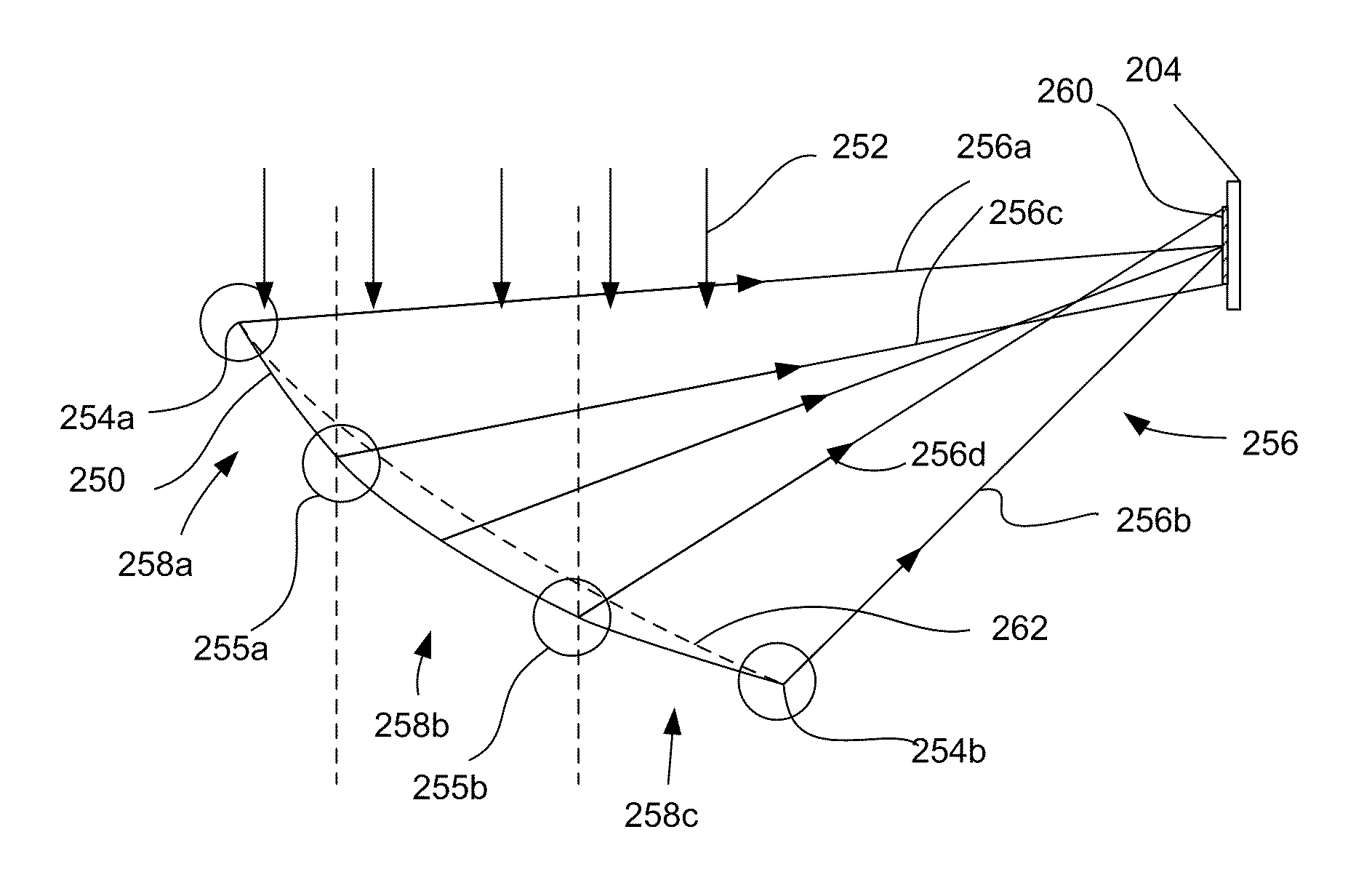
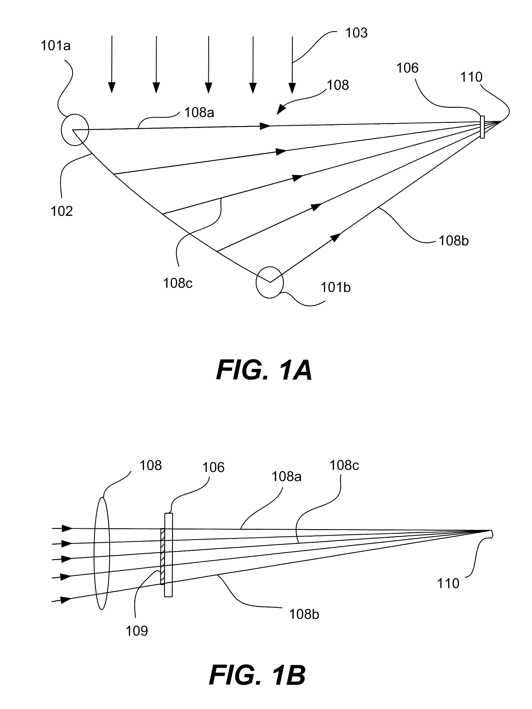
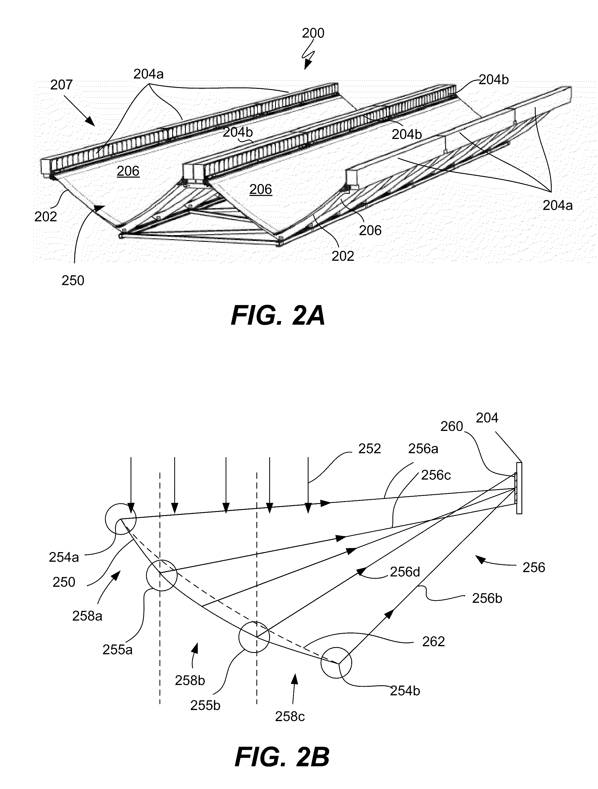
[0028]The present invention relates generally to concentrating photovoltaic (CPV) systems. Various aspects of the present invention relate to a reflective surface that concentrates sunlight onto a solar receiver in a largely non-imaging manner. The reflective surface is arranged to help minimize energy losses attributed to the misalignment of the edges of the reflective surface. Various embodiments of the reflective surface are angularly and spatially continuous and / or distribute light more uniformly across the surface of the solar receiver. Such features can improve the efficiency of solar energy collection and facilitate the manufacture of the reflective surface.

[0029]The present invention represents an improvement upon various reflector designs described in U.S. patent application Ser. No. 12 / 100,726, entitled “Dual Trough Concentrating Solar Photovoltaic Module,” filed Apr. 10, 2008, which is incorporated herein in its entirety for all purposes and is referred to hereinafter as ...


PUM


Abstract

Concentrating solar collector systems that utilize a concentrating reflector to direct incident solar radiation to a solar receiver are described. In one aspect, the reflective surface is arranged to direct light to the receiver in a non-imaging manner in which the solar rays reflected from the opposing edges of the reflective surface are generally directed towards a central portion of the solar receiver. Rays reflected from selected central portions of the reflective surface are directed closer to the edges of the receiver than the solar rays reflected from the edges of the reflective surface. The described reflectors are generally intended for use in solar collector systems that track movements of the sun along at least one axis.

Description

CROSS REFERENCE TO RELATED APPLICATIONS[0001]This application claims the priority of U.S. Provisional Patent Application No. 61 / 162,125 filed Mar. 20, 2009 which is incorporated herein by reference.BACKGROUND OF THE INVENTION[0002]The highest cost components of a solar photovoltaic system are the solar cells that convert sunlight to electricity by the photoelectric effect. To use these cells more effectively, concentrating photovoltaic systems focus sunlight from a larger aperture onto a smaller cell area. Although concentrating photovoltaic designs use less active cell material, they typically require additional structure such as mirrors, lenses and heat sinks, and are fundamentally limited to utilizing less then all of the total available light. These factors increase cost and system complexity and reduce the optical-to-electrical efficiency over non-concentrating photovoltaic systems.[0003]Although existing concentrating solar photovoltaic systems work well, there are continuing ...

Claims


Application Information

Patent Timeline
Patent Type & Authority Patents(United States)
IPC IPC(8): F24J2/38F24S23/70F24S23/71F24S23/79F24S50/20
CPCF24J2/14H01L31/0547F24J2002/1095Y02E10/52Y02E10/45F24S23/74F24S2023/878Y02E10/40G02B5/10H01L31/04
Inventor FINOT, MARC A.WELLS, JASON R.
Owner SKYLINE SOLAR INC
Why Eureka
Try Eureka