Battery charger operating “all or nothing” with a protective power supply circuit for monolithic integrated circuits using the antenna energy

a protection power supply and battery charger technology, applied in the field of integrated monolithic radiofrequency circuits, can solve the problems of difficult to reconcile battery chargers, difficult to meet certain requirements, space restriction, etc., and achieve the effect of preventing poor operation of the circuit dedicated to recharging the battery and ensuring the precise end of charge voltag

Active Publication Date: 2011-05-31
EM MICROELECTRONIC-MARIN
View PDF18 Cites 9 Cited by
  • Summary
  • Abstract
  • Description
  • Claims
  • Application Information

AI Technical Summary

Benefits of technology

[0019]Thus the important points to satisfy for a contactless battery charger integrated in an integrated radiofrequency circuit, are satisfied, namely being integrated in a monolithic circuit without any external components, ensuring a precise end of battery charge voltage while avoiding overcharging, whatever the level of energy received and the temperature at which the charging occurs, and charging with a virtually constant calibrated current during the entire battery charge period.
[0020]It is another object of the present invention to overcome the constraint as to the flexibility of use of various types of battery, i.e. to be able to use several types of battery, or in the extreme, to avoid using the battery for the final device, while keeping the same type of integrated circuit. For this purpose, the reference quantity representative of the end of battery charge can be adjusted depending upon the type of battery used. Moreover, the battery charger advantageously takes the energy it needs to operate from the radiofrequency signals and not from the battery, which means that charging starts quickly while offering a still wider choice for the type of battery that can be used.
[0022]It will be noted that the voltage comparator between the battery voltage and the reference voltage, arranged in the battery charger, is not disturbed by the consumption of energy for recharging the battery insofar as the battery is not charger if there is not enough energy to allow the rest of the circuit to operate. Thus, poor operation of the circuit dedicated to recharging the battery is prevented, which thus means that a precise end of charge voltage can always be ensured.
[0024]The integrated circuit can also operate with a different energy source from a battery, for example originating from the received radiofrequency signals. It will be noted, in this regard, that as the battery is not the only energy source of the circuit, it will consequently not directly power all of the operating units of the integrated circuit. Thus, the battery charger is not directly connected between the energy source, here the antenna associated with the circuit and the power supply of the operating units of the circuit. This arrangement enables the integrated circuit to be started very quickly in the presence of a field if the battery is empty and thereby either to use large capacity batteries or not to use the battery at all and to replace it with nothing in the case of cheaper versions of the final application.

Problems solved by technology

One of the main challenges thus lies in the difficulty of fulfilling certain requirements, for the battery charger, which are not easy to reconcile with the use of monolithic integrated circuits.
These constraints include the restriction of space, which requires avoiding the use of external components for the battery charger.
There are also constraints of precision and reliability, both as regards the end of charge voltage of the battery, which must be well defined, and the charging current intensity in order to prevent damaging the battery.

Method used


Image

  • Battery charger operating “all or nothing” with a protective power supply circuit for monolithic integrated circuits using the antenna energy
  • Battery charger operating “all or nothing” with a protective power supply circuit for monolithic integrated circuits using the antenna energy
  • Battery charger operating “all or nothing” with a protective power supply circuit for monolithic integrated circuits using the antenna energy

Examples


Embodiment Construction

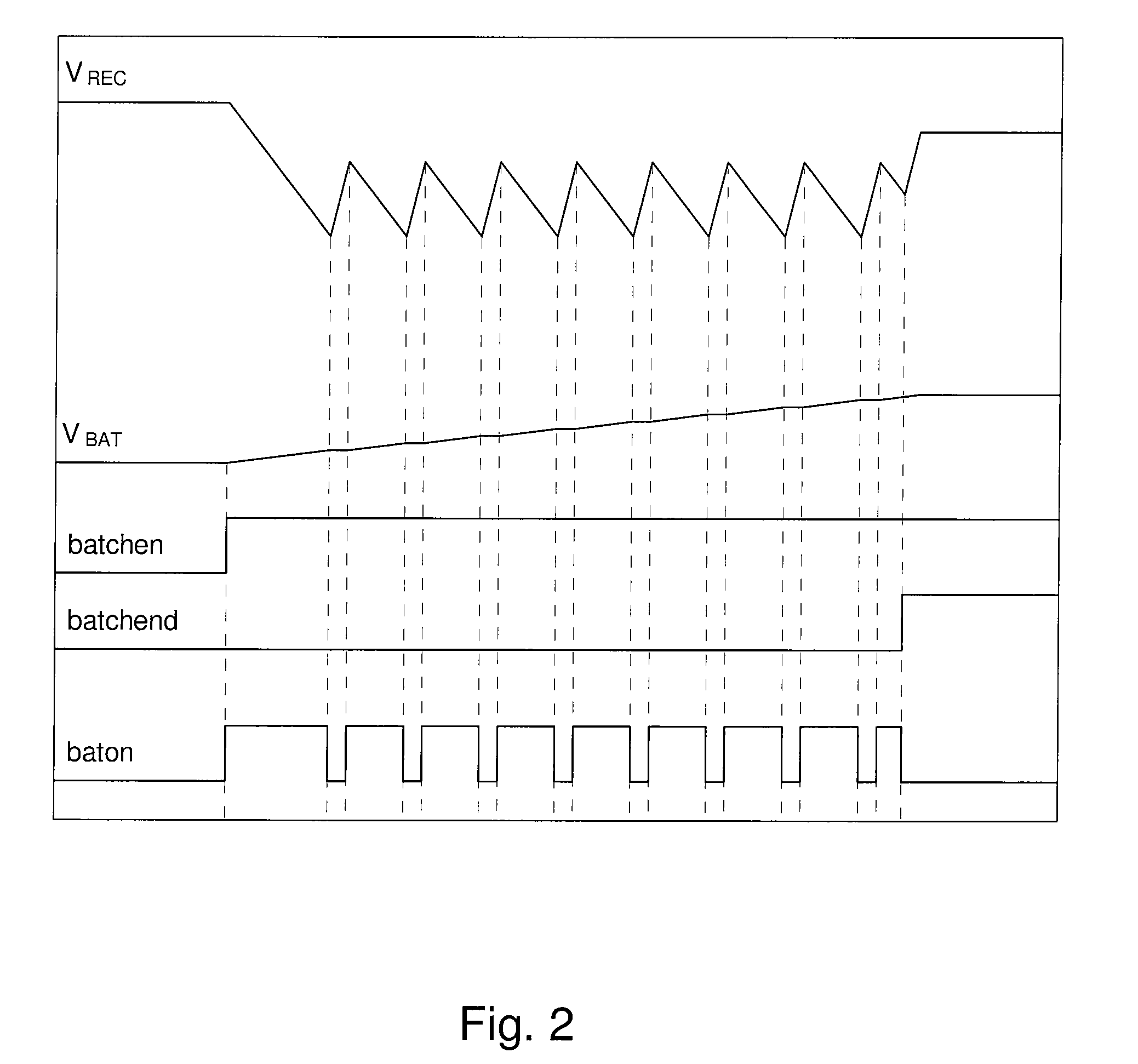
[0034]The present invention, which will now be presented, is given purely by way of non-limiting illustration with reference to FIGS. 1 to 6. The solution proposed consists in finding a suitable structure for a battery charger integrated in a monolithic integrated circuit, which answers the specifications but without exhibiting the numerous drawbacks encountered in the prior art. The battery charger structure developed here therefore operates in an “all or nothing” system, i.e. by switching to charging the battery in the “ON” mode and to not charging the battery in the “OFF” mode.

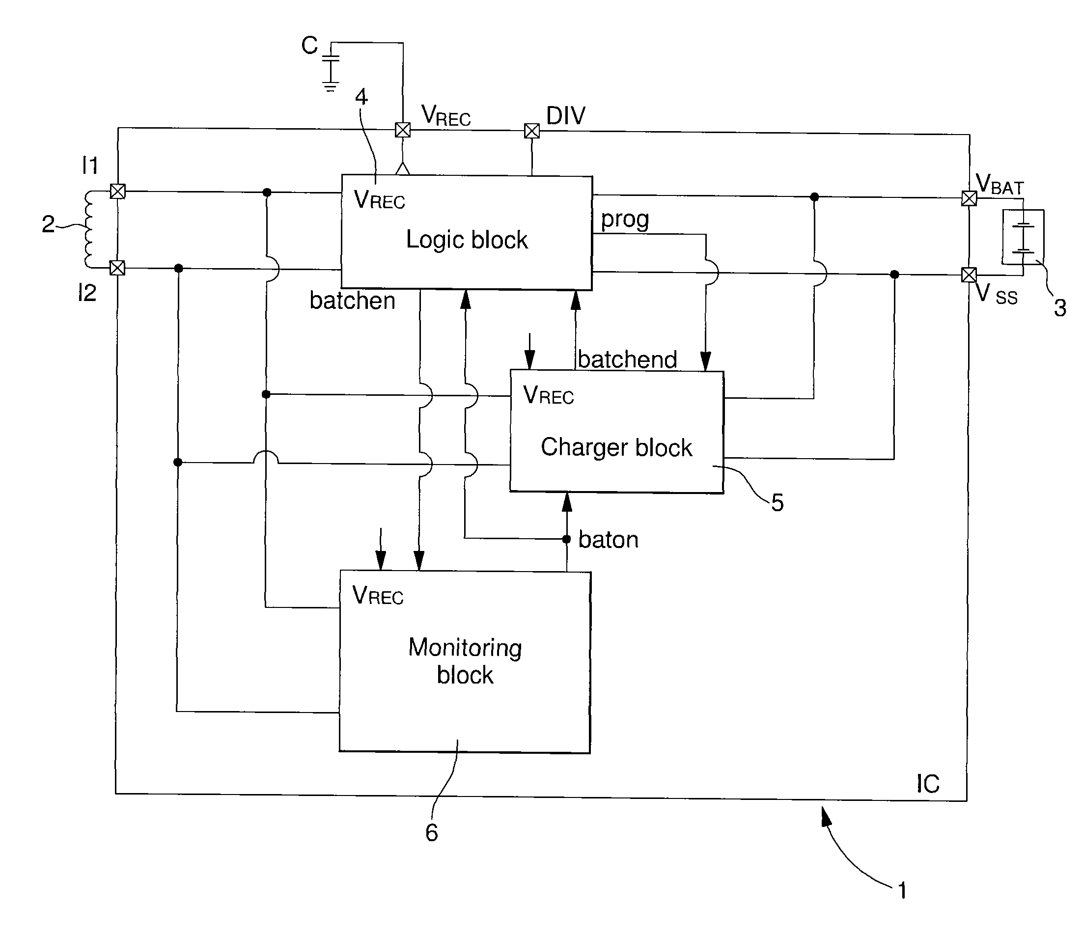
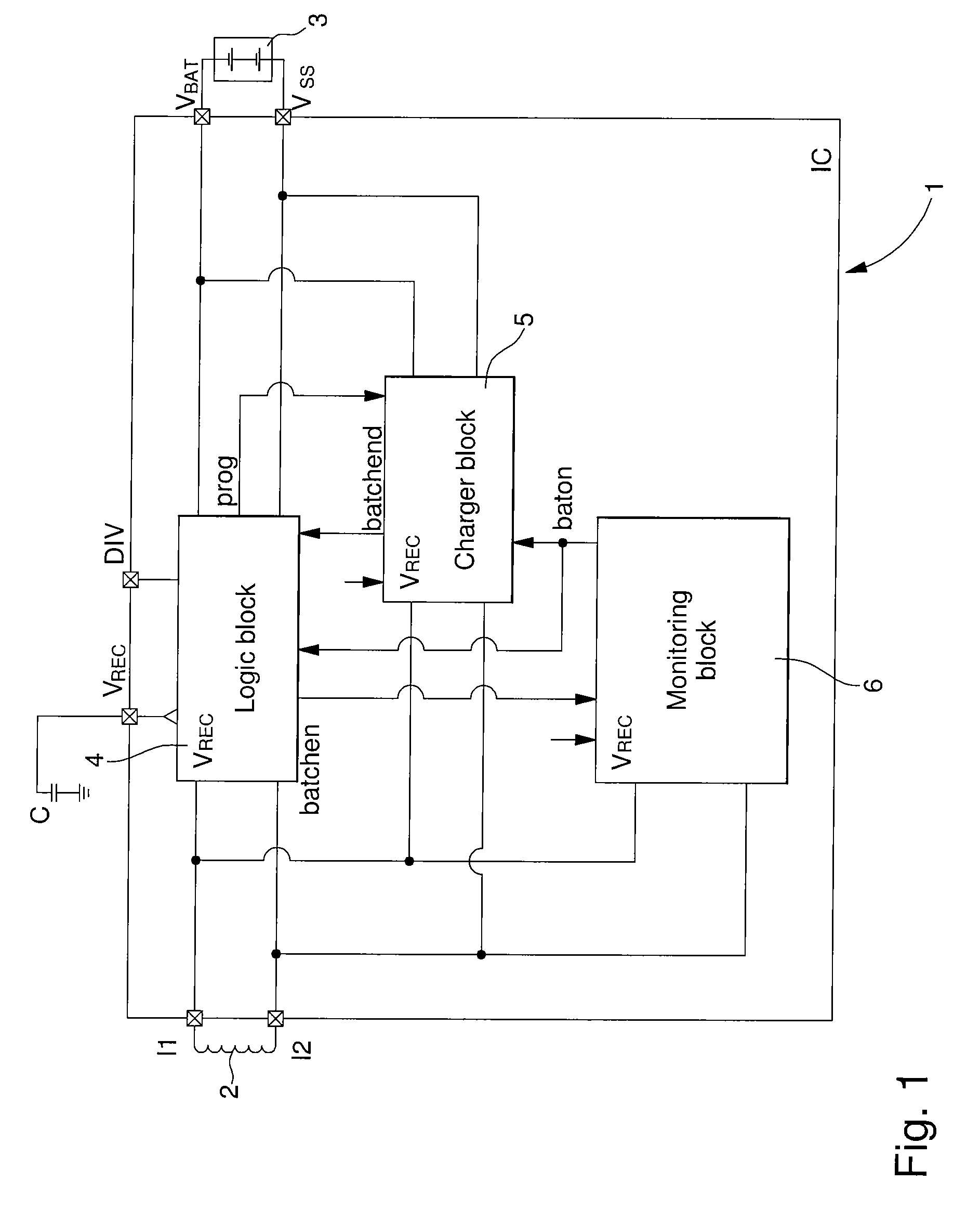
[0035]FIG. 1 shows a block diagram of an integrated radiofrequency circuit according to a preferred embodiment of the invention. The radiofrequency circuit includes a monolithic integrated circuit IC 1. The components outside monolithic integrated circuit 1 are limited to the antenna 2 (or antennae if there are several), the capacitors (not all shown) for uncoupling the various internal supply voltages and ...


PUM


Abstract

An integrated radiofrequency circuit (1) is provided that includes an antenna (2) for receiving radiofrequency signals, a rechargeable battery (3) and a battery charger (5) using the radiofrequency signals to charge said battery. The circuit is characterized in that the battery charger is integrated in the same substrate as the integrated radiofrequency circuit and in that the battery charger includes a calibrating mechanism, a current source calibrated by the calibrating mechanism and delivering a charge current of constant maximum intensity drawn from the received radiofrequency signals, and a comparator between a reference quantity representative of the end of battery charge level and a variable quantity representative of the battery charge level supplying at output a control signal (batchend) for charging or not charging the battery.

Description

[0001]This application claims priority from European Patent Application No. 06127002.1, filed Dec. 22, 2006, the entire disclosure of which is incorporated herein by reference.FIELD OF THE INVENTION[0002]The present invention concerns, generally, an integrated monolithic radiofrequency circuit including an antenna for receiving radiofrequency signals, a rechargeable battery and a battery charger integrated in the monolithic circuit using the radiofrequency signals to charge the battery. The invention concerns, more specifically, the battery charger operating “all or nothing” integrated in the monolithic circuit.BACKGROUND OF THE INVENTION[0003]Radiofrequency circuits including an antenna receiving radiofrequency signals and powered by a rechargeable battery are known generally from the prior art. Incorporating a battery charger that uses the energy received via the radiofrequency signals to charge the battery, in order to avoid dismantling the batter, is also known.[0004]One example...

Claims


Application Information

Patent Timeline
Patent Type & Authority Patents(United States)
IPC IPC(8): H02J7/00G06K19/06
CPCG06K19/0702H02J7/0077G06K19/0723G06K19/0707H02J50/20H02J7/00712
Inventor LAMOTHE, CHRISTIAN
Owner EM MICROELECTRONIC-MARIN
Why Eureka
Try Eureka