Communication apparatus enabling temporal coexistence of systems

a technology of communication apparatus and temporal coexistence, applied in the field of communication apparatus, can solve the problems of noise of power line modems, power line modems employing one communication scheme, and best-effort communication which cannot guarantee the use of bands, etc., to avoid waste, prevent overlapping of master functions, and high efficiency

Active Publication Date: 2011-05-31
PANASONIC CORP
View PDF10 Cites 4 Cited by
  • Summary
  • Abstract
  • Description
  • Claims
  • Application Information

AI Technical Summary

Benefits of technology

[0034]According to the present invention, a QoS type communication system and a best-effort type communication system can coexist in accordance with priorities given to the respective communication systems. Thereby, when a plurality of power line communication modems having different communication schemes are introduced into a user's home, it is possible to select which communication scheme type of power line communication modem is caused to manage communication. In addition, it is possible to prevent overlapping of master functions, and select which power line communication modem has a service which should be given priority, for each user. Also, even when either the master or the slave becomes inactive, it is possible to achieve coexistence in which a power line can be used with high efficiency, avoiding waste.

Problems solved by technology

Therefore, only best-effort communication which does not guarantee a band to be used can be achieved.
For such services requiring guarantee of QoS, best-effort communication does not satisfy required quality.
However, since all power lines provided in a home are connected to a distribution switchboard, when power line modems employing different communication schemes are used in the same home, a signal which is transmitted to a power line by a power line modem employing one communication scheme is noise for a power line modem employing another communication scheme.
Therefore, when power line modems employing different communication schemes perform communications simultaneously, the communications interfere with each other or all the communications are disabled as illustrated in (c) of FIG. 20, resulting in a significant reduction in communication rate.
However, the above-described conventional apparatus for managing data communication apparatuses does not have means for correctly determining how much communication time is provided to a QoS type power line communication system and with what timing the communication time is provided to the system so as to enable guarantee of QoS.
Also, the data communication apparatus managing apparatus does not have means with which a QoS controller of a QoS type power line communication system determines how much time is provided to another power line communication system.
Therefore, the QoS controller does not determine how much time can be provided to a power line modem of a system to which the QoS controller belongs, and therefore, cannot determine whether or not a request for a service can be accepted.
Therefore, it is not possible to achieve coexistence of a QoS type power line communication system and a best-effort type power line communication system.

Method used


Image

  • Communication apparatus enabling temporal coexistence of systems
  • Communication apparatus enabling temporal coexistence of systems
  • Communication apparatus enabling temporal coexistence of systems

Examples


first embodiment

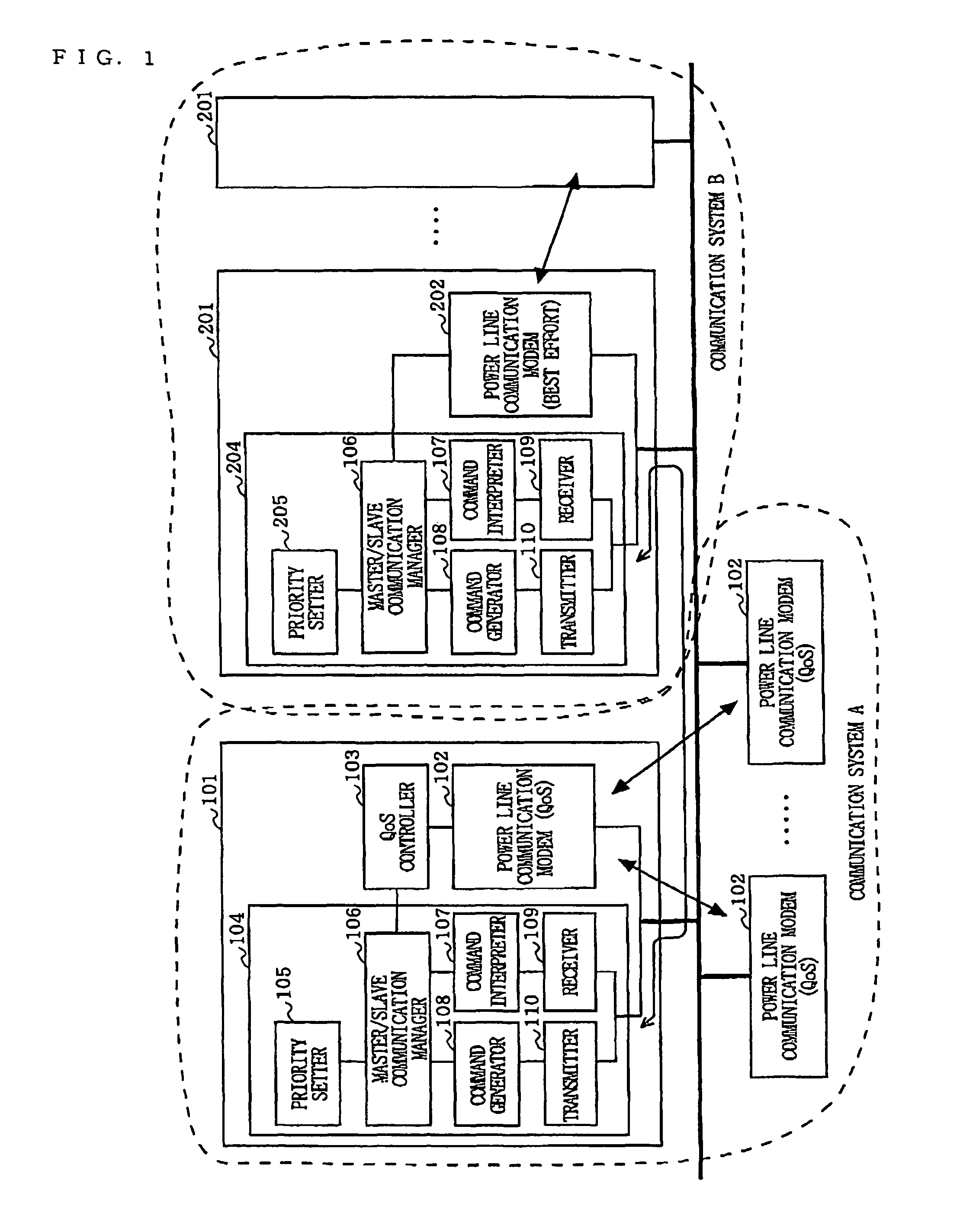
[0057]FIG. 1 is a diagram illustrating a configuration of a power line communication system according to a first embodiment of the present invention. In the power line communication system of the first embodiment, a QoS type communication system A and a best-effort type communication system B are connected to each other via a power line. In this example, the communication system A is a master and the communication system B is a slave.

[0058]The communication system A comprises a power line communication control modem 101 including a power line communication modem 102, a QoS controller 103 and a coexistence controller 104, and a plurality of power line communication modems 102. The coexistence controller 104 performs various communications so as to achieve a control of coexistence with other power line communication systems. The coexistence controller 104 comprises a priority setter 105, a master / slave communication manager 106, a command interpreter 107, a command generator 108, a re...

second embodiment

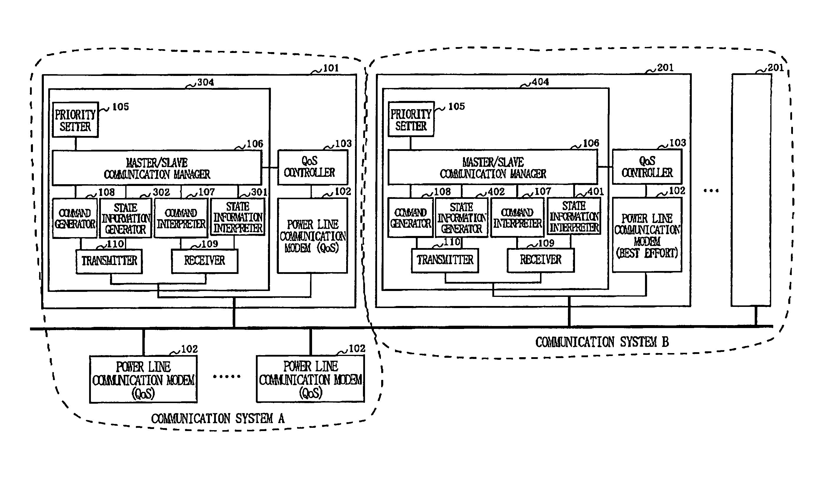
[0090]FIG. 13 is a diagram illustrating a configuration of a power line communication system according to a second embodiment of the present invention. In the power line communication system of the second embodiment of FIG. 13, a QoS type communication system A and a best-effort type communication system B are connected to each other via a power line. The communication system A comprises a power line communication control modem 101 including a power line communication modem 102, a QoS controller 103 and a coexistence controller 304, and a plurality of power line communication modems 102. The communication system B comprises a power line communication control modem 201 including a power line communication modem 202 and a coexistence controller 404, and a plurality of power line communication modems 202.

[0091]As can be seen from comparison of FIG. 1 and FIG. 13, the communication system A of the second embodiment further comprises a state information interpreter 301 and a state inform...


PUM


Abstract

A coexistence controller which performs management and control of time division for coexistence, is provided in a power line communication modem which has a function as a QoS controller for a QoS type communication system and a power line communication modem for a best-effort type communication system. In the QoS type communication system, by controlling allocation of a communication band in accordance with priorities given to the communication systems by cooperation of the coexistence controller and the QoS controller, the power line communication systems having different schemes can coexist.

Description

BACKGROUND OF THE INVENTION[0001]1. Field of the Invention[0002]The present invention relates to a communication apparatus which enables temporal coexistence of systems, and more particularly to, a communication system which enables coexistence of a plurality of different communication schemes (a communication system which guarantees Quality of Service (QoS) and a communication system which performs best-effort communication) on the same communication medium, such as a power line or the like.[0003]2. Description of the Background Art[0004]Power Line Communications (PLC) has attracted attention as a technology for connection of a network apparatus, such as a broadband router or the like, so as to access from a Personal Computer (PC) or the like in a home to the Internet. In the power line communication, since an existing power line is used as a communication medium, it is not necessary to construct a new infrastructure, and high-speed communication can be achieved only by inserting a...

Claims


Application Information

Patent Timeline
Patent Type & Authority Patents(United States)
IPC IPC(8): H04L12/43
CPCH04B3/542H04W74/04H04B2203/5408H04B2203/5445H04B2203/5479H04B2203/5441H04B3/54
Inventor KUROBE, AKIOIKEDA, KOJIKURODA, GOKOGA, HISAOIGATA, YUJI
Owner PANASONIC CORP
Why Eureka
Try Eureka