X-ray CT apparatus and image processing apparatus

a technology of x-ray ct and image processing, applied in image enhancement, angiography, instruments, etc., can solve the problem of unfavorable elimination of unsharpness in the surroundings of high-contrast regions, and achieve the effect of relieving unsharpness

Inactive Publication Date: 2011-05-31
TOSHIBA MEDICAL SYST CORP
View PDF13 Cites 23 Cited by
  • Summary
  • Abstract
  • Description
  • Claims
  • Application Information

AI Technical Summary

Benefits of technology

[0008]An object of the present invention is to relieve unsharpness which appears in the surroundings of an object of high X-ray attenuation coefficient in case of displaying the X-ray absorption distribution image of the interior of a patient as has been obtained by an X-ray CT apparatus.

Problems solved by technology

With this method, however, it has been impossible to favorably eliminate the unsharpness of the surroundings of the high-contrast region (refer to JP-A-10-40372).

Method used


Image

  • X-ray CT apparatus and image processing apparatus
  • X-ray CT apparatus and image processing apparatus
  • X-ray CT apparatus and image processing apparatus

Examples


first embodiment

[0023]Now, the first embodiment of the present invention will be described.

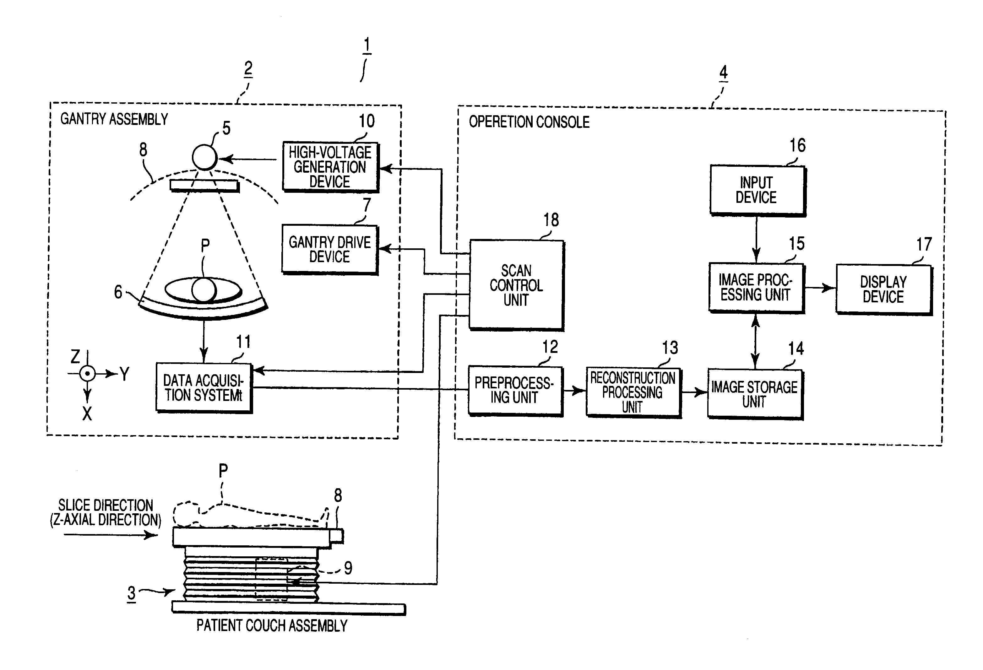
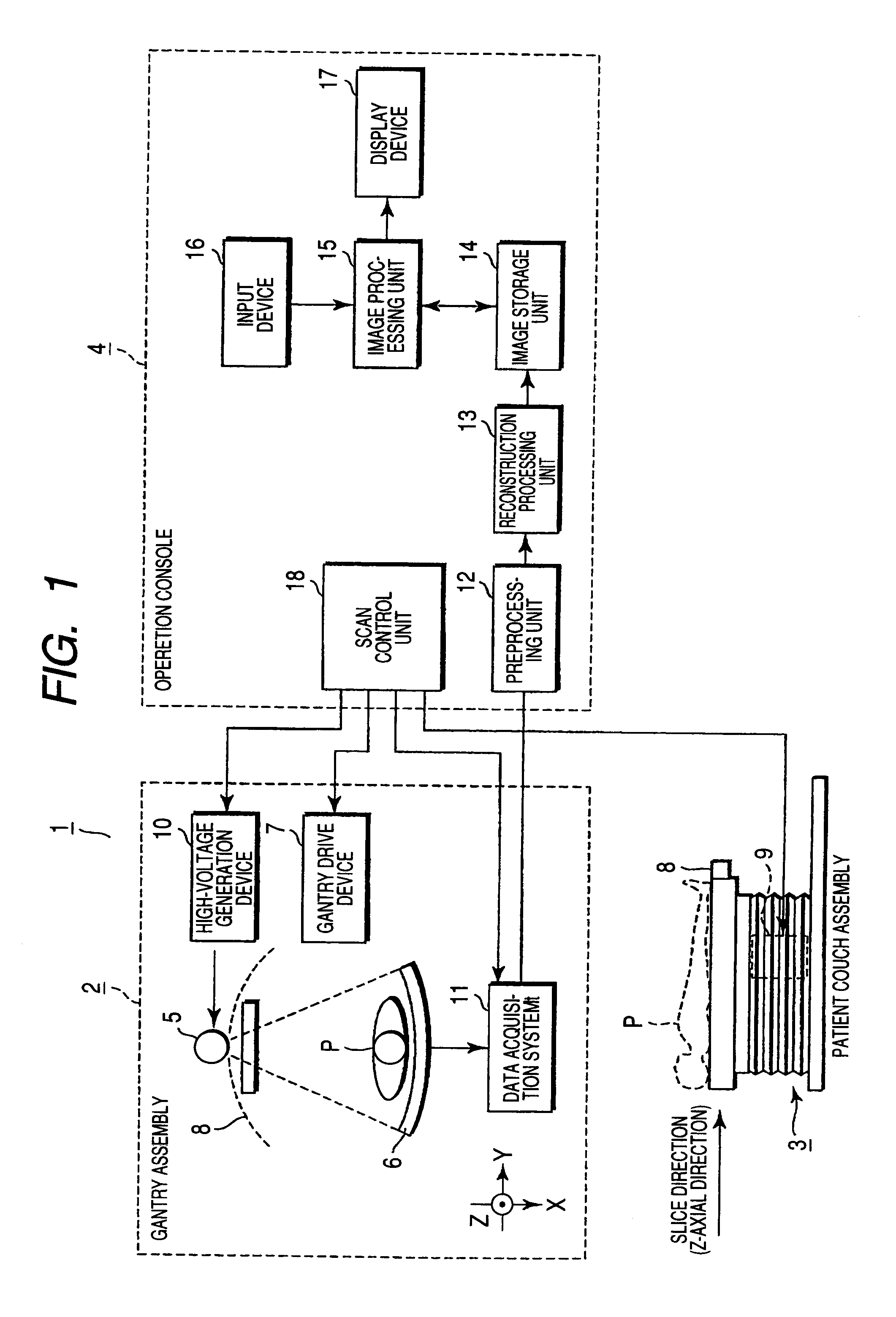
[0024]FIG. 1 is a block diagram of an X-ray CT apparatus according to the first embodiment. The X-ray CT apparatus 1 includes a gantry 2 which is configured in order to acquire projection data on a patient, a patient couch 3 which serves to carry and move the patient P, and an operation console which serves to perform inputting and image display for operating the X-ray CT apparatus 1.

[0025]The gantry 1 has an X-ray tube 5 and an X-ray detector 6. The X-ray tube 5 and the X-ray detector 6 are mounted on a ring-shaped rotation frame 8 which is driven to rotate by a gantry drive device 7. The patient couch 3 includes a top 8 on which the patient is placed, and a top drive device 9 which serves to move the top 8. The rotation frame 8 has an opening at its central part. The patient P placed on the top 8 is inserted into the opening. Incidentally, the axis of the center of the rotation of the rotation frame 8 is de...

second embodiment

[0042]Now, the second embodiment of the invention will be described. Incidentally, the same parts as in the first embodiment shall be omitted from description.

[0043]The second embodiment consists in that similar substances in an image are automatically classified by a clustering process in order to facilitate identifying the similar substances. It is known under ideal conditions that a plaque or lipide exhibits a CT number of −100 to 50, that a vascular wall exhibits a CT number of 50 to 129, and that a contrast medium contained in a blood flow exhibits a CT number of 130 to 350. In an actual examination, however, the CT numbers fluctuate under the influences of the body build of a patient, beam hardening, a reconstruction function, the sizes of the substances, the states of substances outside a region of interest, the concentration of the contrast medium, etc. In a method which performs regional extraction (regional division), such fluctuations of the CT numbers cannot be coped wit...


PUM


Abstract

An X-ray CT apparatus includes a unit which extracts a high-contrast region of comparatively high X-ray attenuation coefficient from an image, units which generate an unsharp image concerning the high-contrast region, on the basis of the position of the extracted high-contrast region and a point spread function peculiar to the apparatus, and a unit which subtracts the unsharp image from the original image in order to generate a low-contrast image concerning a low-contrast region of comparatively low X-ray attenuation coefficient.

Description

CROSS-REFERENCE TO RELATED APPLICATIONS[0001]This is a Continuation Application of PCT application No. PCT / JP2005 / 021588, filed Nov. 24, 2005, which was published under PCT Article 21(2) in Japanese.[0002]This application is based upon and claims the benefit of priority from prior Japanese Patent Applications No. 2004-342272, filed Nov. 26, 2004; and No. 2004-342273, filed Nov. 26, 2004, the entire contents of both of which are incorporated herein by reference.BACKGROUND OF THE INVENTION[0003]1. Field of the Invention[0004]The present invention relates to an X-ray CT apparatus and an image processing apparatus which generate an image within a patient, on the basis of projection data obtained by irradiating the patient with X-rays.[0005]2. Description of the Related Art[0006]The progress of X-ray CT apparatuses is remarkable, and in compliance with the eager desire of medical treatment sites to radiograph a patient at a higher precision (higher resolution) and in a wider range, a mul...

Claims


Application Information

Patent Timeline
Patent Type & Authority Patents(United States)
IPC IPC(8): G06K9/00H05G1/64A61B6/00A61B6/03
CPCA61B5/02007A61B6/481A61B6/504G06T5/004G06T7/40G06T11/008G06T7/0012G06T7/0081G06T5/20A61B6/032G06T2207/30004G06T2211/404G06T7/11
Inventor OKAMOTO, YOSUKENAKANISHI, SATORU
Owner TOSHIBA MEDICAL SYST CORP
Why Eureka
Try Eureka