
Vacuum wire tensioner for wire bonder

a vacuum wire tensioner and wire tensioner technology, which is applied in the direction of soldering apparatus, manufacturing tools,auxillary welding devices, etc., can solve the problems of high volume of compressed, disturbance of whipping, and impose torque, so as to reduce the introduction of contaminants into the wire tensioner and avoid the need for frequent cleaning of the wire tensioner

Active Publication Date: 2011-06-07
ASMPT SINGAPORE PTE LTD
View PDF10 Cites 4 Cited by
  • Summary
  • Abstract
  • Description
  • Claims
  • Application Information

AI Technical Summary

Benefits of technology

[0010]It is thus an object of the invention to seek to achieve the benefits of using a vacuum wire tensioner while at the same time reducing the introduction of contaminants into the wire tensioner and avoiding the need for frequent cleaning of the wire tensioner.

Problems solved by technology

Use of a compressed air to generated the aforesaid pulling force has the disadvantage that, on its own, a high volume of compressed is required to generate a sufficient force to move the wire.
As a result, the problem of turbulence created in the air flow as it exits from the tensioner causes undesirable wire vibration and spinning that may impose torque and whipping disturbances to the wire being fed through the wire tensioner.
Furthermore, the prior art design generates compressed air directly into the passage where the wire is located, which further aggravates the problems of wire vibration and spinning when compressed air is injected directly onto the wire.
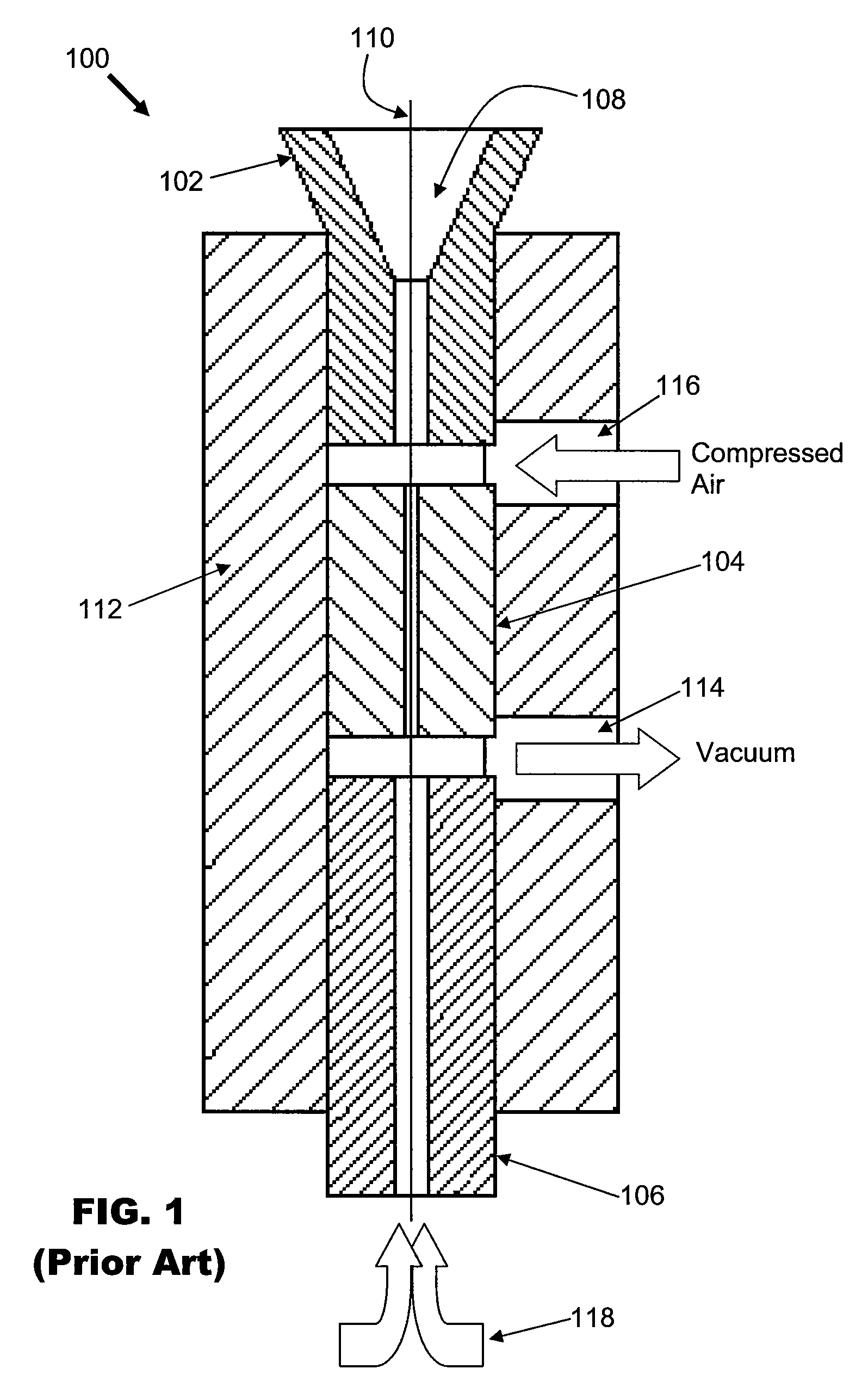
However, a problem with the conventional design illustrated in FIG. 1 is that ambient air 118 containing contaminants generated from the surrounding during wire bonding are sucked into the central bore 108 of the wire tensioner 100 through the mouth of the wire outlet 106.
After a period of usage, the inner components of the wire tensioner may become clogged with contaminants, and this results in the necessity for frequent cleaning of the wire tensioner 100.
Frequent cleaning is inconvenient to the operator and leads to down-time of the wire bonding apparatus.

Method used


Image

  • Vacuum wire tensioner for wire bonder
  • Vacuum wire tensioner for wire bonder
  • Vacuum wire tensioner for wire bonder

Examples


Embodiment Construction

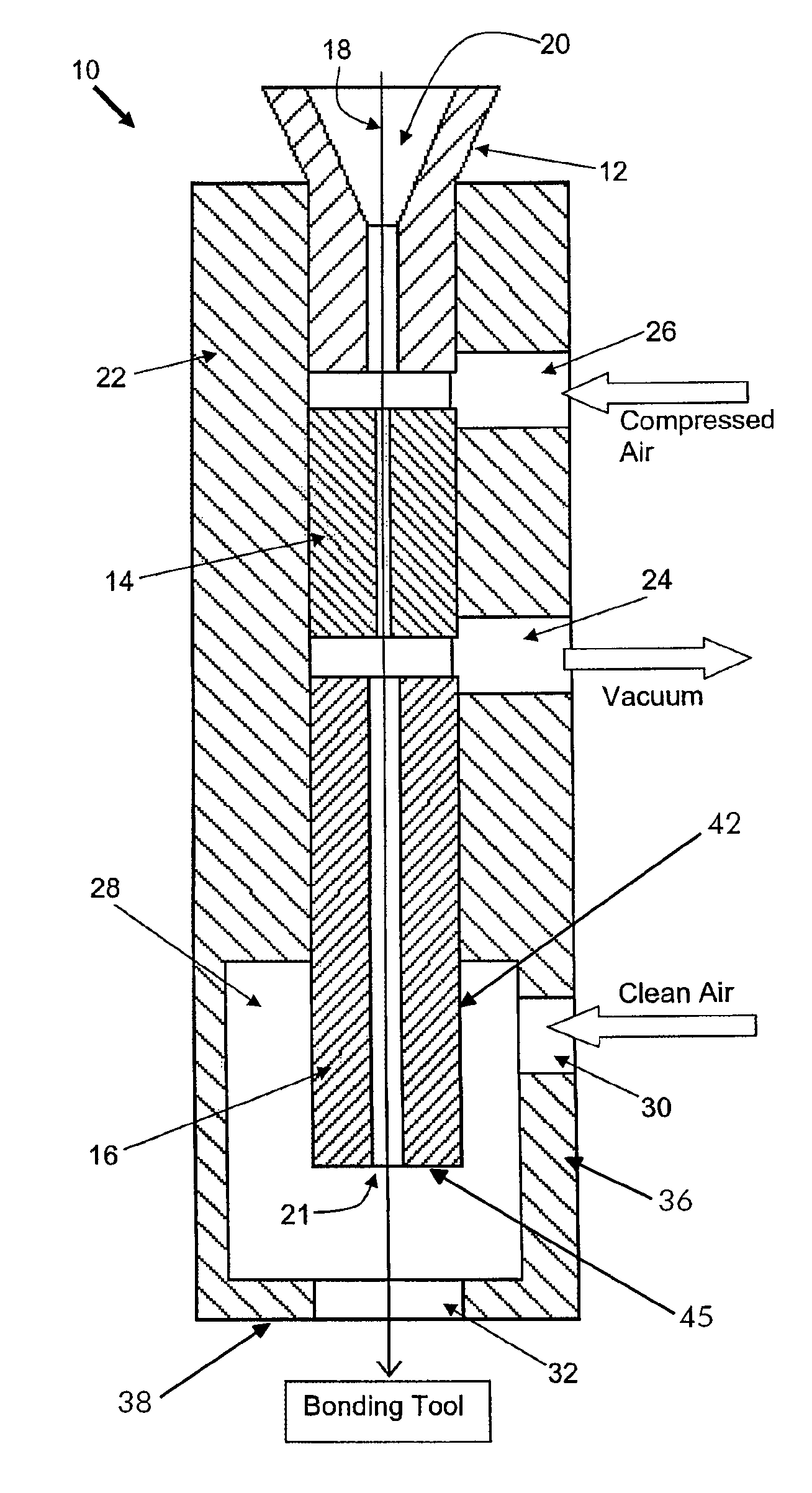
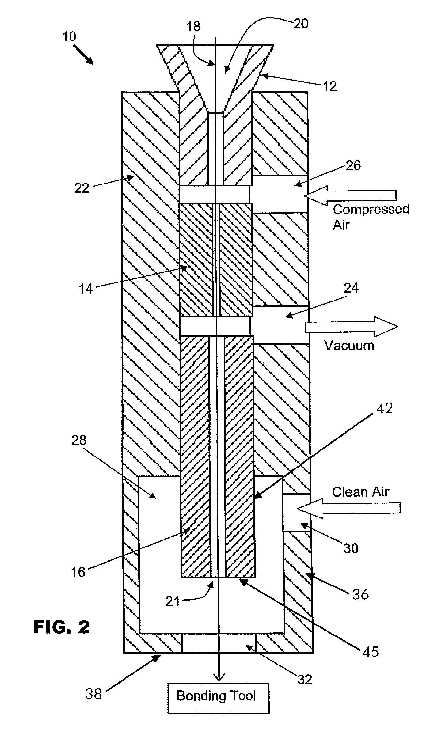
[0017]FIG. 2 is a schematic cross-sectional view of a vacuum wire tensioner according to the preferred embodiment of the invention. The wire tensioner 10 comprises a tubular body through which bonding wire is receivable, the tubular body including a wire inlet 12, inner tube 14 and wire outlet 16. The tubular body has a central bore 18 extending through the respective wire inlet 12, inner tube 14 and wire outlet 16. Bonding wire 20, such as gold wire, is led through the central bore 18 from the wire inlet 12 to the wire outlet 16. The bonding wire 20 is extended from a bore outlet 21 located at an end of the wire outlet 16 portion of the tubular body towards a capillary (not shown) of a bonding tool. The wire inlet 12, inner tube 14 and wire outlet 16 are substantially enclosed by a wire tensioner housing 22, which also serves as a means to secure the wire tensioner 10 to a wire bonding apparatus by securing the housing 22.

[0018]Near a mid-point of the wire tensioner housing 22, a v...


PUM

PropertyMeasurementUnit
widthaaaaaaaaaa
widthaaaaaaaaaa
widthaaaaaaaaaa

Abstract

A wire tensioner is provided for a wire bonder, the wire tensioner comprising a tubular body having a bore through which bonding wire is receivable and a bore outlet at an end of the tubular body from which the bonding wire is extendable towards a bonding tool. A chamber is formed next to the bore outlet that substantially encloses the bore outlet, the chamber including an air inlet connected to it that is operative to introduce clean air into the chamber. A vacuum outlet is connected to a side of the tubular body and is in fluid communication with the chamber via the bore, the vacuum outlet being operative to draw air from the bore outlet through the bore whereby to pull the wire.

Description

FIELD OF THE INVENTION[0001]The invention relates to a wire bonding apparatus for making wire connections between electronic devices, and in particular, to a wire tensioner for controlling the feeding of wire in such wire bonding apparatus.BACKGROUND AND PRIOR ART[0002]In a wire bonding process, electrically conductive wires are bonded between electrical bonding pads found on semiconductor devices, such as between a semiconductor die and a substrate onto which the die is attached. The substrate is usually a semiconductor leadframe. The electrical connection could also be made between bonding pads found on separate semiconductor dice. The bond is formed by a bonding tool which may be in the form of a capillary attached to an ultrasonic transducer for generating ultrasonic energy to the capillary tip.[0003]Wire is continually fed to the capillary in order to make wire connections. The wire feeding system may comprise a clamp that is operative to secure the wire relative to the bonding...

Claims


Application Information

Patent Timeline
Patent Type & Authority Patents(United States)
IPC IPC(8): B23K37/00
CPCB23K20/004H01L24/78H01L24/85H01L24/45H01L2924/01033H01L2924/00014H01L2224/45144H01L2224/78302H01L2224/851H01L2924/01005H01L2924/01079H01L2924/01082H01L2224/48H01L2224/78631H01L2224/85205Y10S228/904H01L2924/00
Inventor KWAN, KA SHING KENNYZHANG, YUEWONG, YAM MO
Owner ASMPT SINGAPORE PTE LTD
Learn More