Structure of vehicle end section

a technology of end sections and end sections, applied in the direction of roofs, bumpers, pedestrian/occupant safety arrangements, etc., can solve the problem of not being able to effectively receive collision load, and achieve the effect of reducing repair costs

Inactive Publication Date: 2011-06-07
TOYOTA JIDOSHA KK
View PDF21 Cites 8 Cited by
  • Summary
  • Abstract
  • Description
  • Claims
  • Application Information

AI Technical Summary

Benefits of technology

[0006]Since the cantilevered portions are readily bent, there were cases where another vehicle colliding offset with the under protector turned around to the side, so as to damage the side part of the vehicle body. For this reason, there were demands for further improvement in these aspects. An object of the present invention is therefore to provide a vehicle end structure capable of more reliably receiving a load upon collision, in a vehicle body of the frame construction.
[0008]This vehicle end structure employs the brackets and the outer pillar members to join the two ends of the cross member (a member corresponding to the under protector or the like) to the frame members. For this reason, the portions outside the inner pillar members are prevented from being deformed upon a collision, and a colliding object in an offset collision can be effectively prevented from turning around to the side of the vehicle. In addition, the pair of frame members as structural members can not receive only the colliding force exerted on the pair of inner pillar members but can also receive the colliding force exerted on the parts outside the inner pillar members, through the brackets and outer pillar members. As a result, the vehicle having this vehicle end structure receives the collision load by the framework and realizes good anti-crash performance.
[0010]Since this vehicle end structure utilizes the brackets for mounting of the body to join the portions near the ends of the cross member to the frame members, new members to be prepared are only the pair of outer pillar members. For this reason, the vehicle end structure of the present invention can be constructed with good space efficiency and in a simple configuration.
[0011]Furthermore, the vehicle end structure according to the present invention is characterized as follows: in the aforementioned vehicle end structure, the cross member is constructed as an under protector for protecting a lower surface of the vehicle body from contact with a road surface.
[0012]Since in this vehicle end structure the cross member is formed as an under protector, the vehicle end structure of the present invention can be constructed while suppressing an increase in the number of parts.
[0014]Since in this vehicle end structure the energy absorbing members have the rigidity smaller than that of the frame members, only the energy absorbing members are deformed upon a mild collision (including an offset collision) to absorb the energy upon the collision. For this reason, the frame members can still be used even after the collision and repair cost can be reduced.

Problems solved by technology

However, the portions of the under protector located outside the brackets in the vehicle are cantilevered, and thus this configuration failed to effectively receive the collision load upon an offset collision which is the majority of collisions.
Since the cantilevered portions are readily bent, there were cases where another vehicle colliding offset with the under protector turned around to the side, so as to damage the side part of the vehicle body.

Method used


Image

  • Structure of vehicle end section
  • Structure of vehicle end section
  • Structure of vehicle end section

Examples


Embodiment Construction

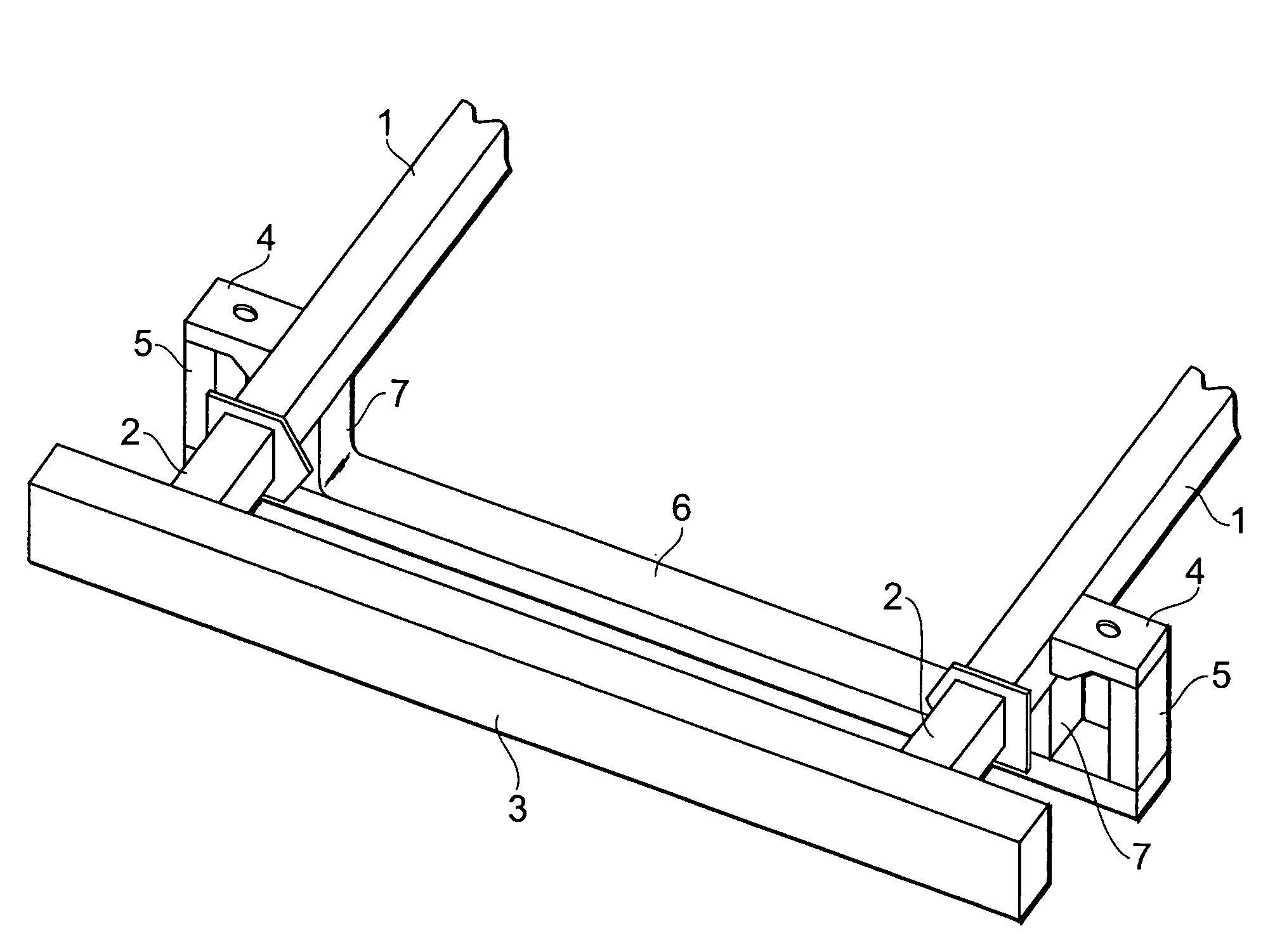
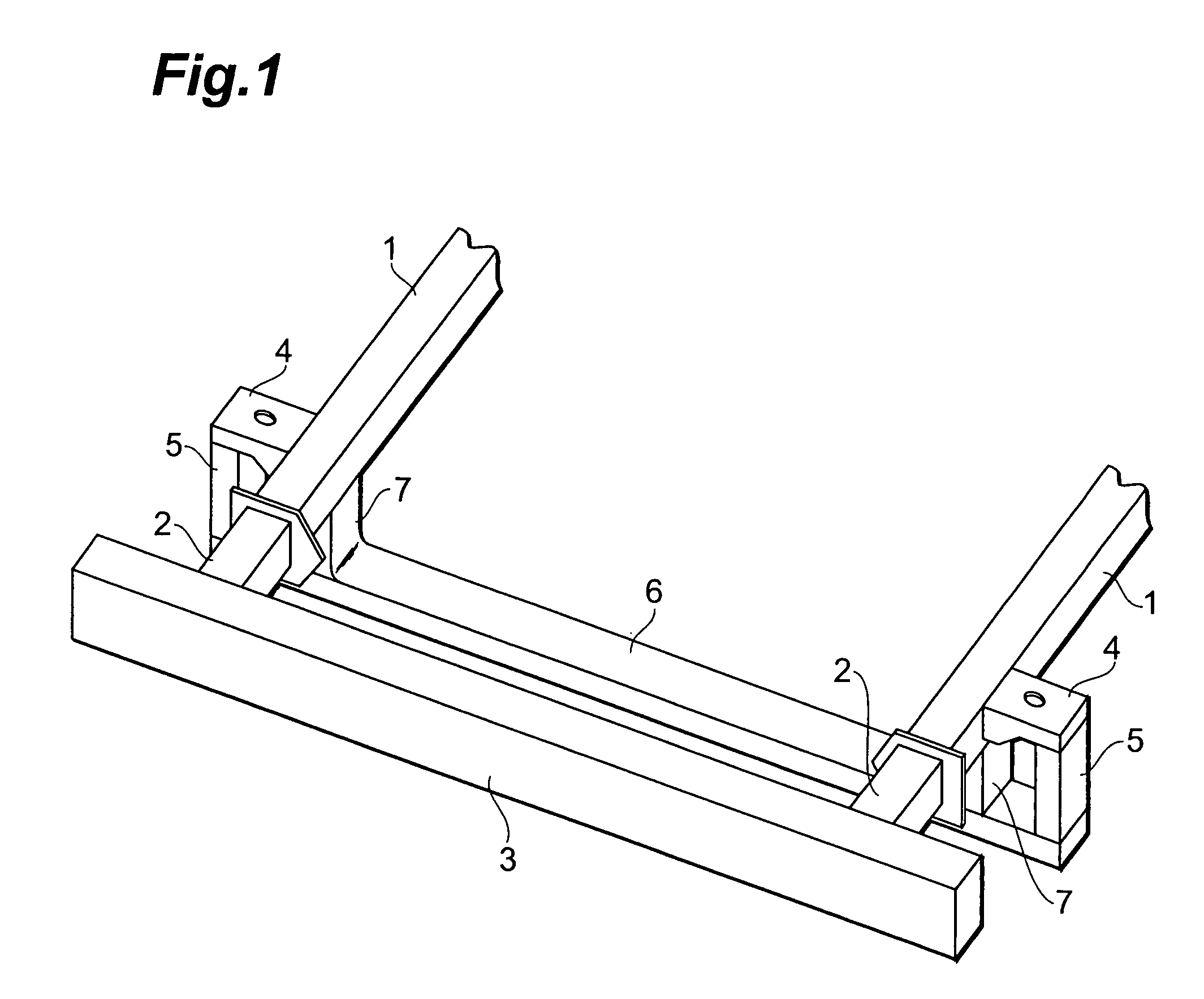
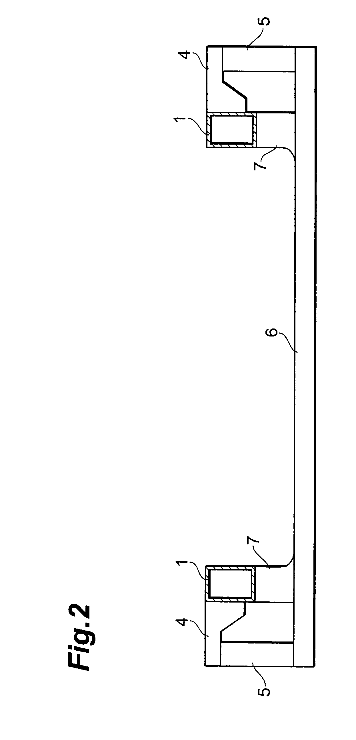
[0018]An embodiment of the vehicle end structure according to the present invention will be described below. FIG. 1 shows an enlarged perspective view of a major part of the vehicle end structure of the present embodiment. FIG. 2 shows a sectional view obtained by cutting a region near front ends of a pair of frame members 1 described later (sectional view of the rear side from the front side of the vehicle). FIGS. 1 and 2 show the vehicle end structure on the front side. A vehicle having the vehicle end structure of the present embodiment is a vehicle of the frame construction. As shown in FIG. 1, a pair of frame members 1 constituting a frame are arranged approximately in parallel with an anteroposterior direction of the vehicle.

[0019]The frame members 1 are depicted only in part on the vehicle front side. Crash boxes 2 are joined to the respective tip portions of the pair of frame members 1. The crash boxes 2 have the rigidity smaller than that of the frame members 1 and are prov...


PUM


Abstract

An object of the present invention is to provide a vehicle end structure capable of more reliably receiving a load upon a collision in a vehicle body of the frame construction. The vehicle end structure of the present invention is one constructed near a front end (or rear end) of a framework of a vehicle and is characterized by comprising a pair of body frame members 1 extending in an anteroposterior direction of the vehicle body; a bumper reinforce 3 hung at ends of the pair of frame members 1; a pair of brackets 4 located on the center side of the vehicle with respect to the ends of the pair of frame members 1 and projecting outwardly and laterally from the respective frame members; a pair of outer pillar members 5 extending downward from the respective brackets 4; a cross member 6 hung between the pair of outer pillar members 5; and a pair of inner pillar members 7 joining an upper surface of the cross member 6 to the respective frame members 1.

Description

TECHNICAL FIELD[0001]The present invention relates to a vehicle end structure constructed near a front or rear end of a framework of a vehicle.BACKGROUND ART[0002]The typical construction forms of vehicle body structures include the monocoque construction and the frame construction. The monocoque construction is a construction in which the conventional frame and body are integrally constructed from sheet steel, and is frequently used for passenger cars and the like. On the other hand, the frame construction is a construction in which the body is mounted on a tough framework called a frame. The frame construction is excellent in strength and is frequently used for trucks with a large loading capacity or with a large own weight, recreational vehicles receiving large input from road surfaces, e.g., during running on a rough road, and so on.[0003]A truck has a large vehicle body and thus has a high bumper location. A recreational vehicle also has a rather high bumper location because th...

Claims


Application Information

Patent Timeline
Patent Type & Authority Patents(United States)
IPC IPC(8): B62D25/08
CPCB60R19/12B62D21/152B60R2021/002B60R19/24
Inventor KOSAKA, NAOYA
Owner TOYOTA JIDOSHA KK
Why Eureka
Try Eureka