Device for verifying and monitoring vital parameters of the body

a technology for vital parameters and devices, applied in the field of devices for verifying and monitoring the vital parameters of the human or animal body, can solve the problems of most disadvantages, most hindering doctors, and most obstructed persons being examined, and achieve the effect of being easily carried

Inactive Publication Date: 2011-06-07
SUPER SHINE VENTURES LTD
View PDF17 Cites 21 Cited by
  • Summary
  • Abstract
  • Description
  • Claims
  • Application Information

AI Technical Summary

Benefits of technology

[0005]The aim of the invention is to avoid the disadvantages of known diagnostic and monitoring equipment, by creating a device for a fast diagnosis of the most important vital parameters of the human and animal body, especially the examination of the heart, and/or the lungs in their expansion, condition and ability to function, as well as the constant monitoring of the person being exami

Problems solved by technology

This well-known examination and monitoring equipment is, through the cable connections mentioned above and the separate amplifier units and the analysis equipment and especially through the dimensions of these components, most disadvantageous.
Firstly, the cables cause obstruction the person being examined.
But above all, the doctors are hindered the most, as the equipment is fixed in its location to each person being examined and can not be readily taken by the doctor and, in a short time, be used for other patients.
This diagnosis and monitoring equipment, however still has major disadvantages.
It is technically too complicated and too expensive, through the necessar

Method used


Image

  • Device for verifying and monitoring vital parameters of the body
  • Device for verifying and monitoring vital parameters of the body
  • Device for verifying and monitoring vital parameters of the body

Examples


Embodiment Construction

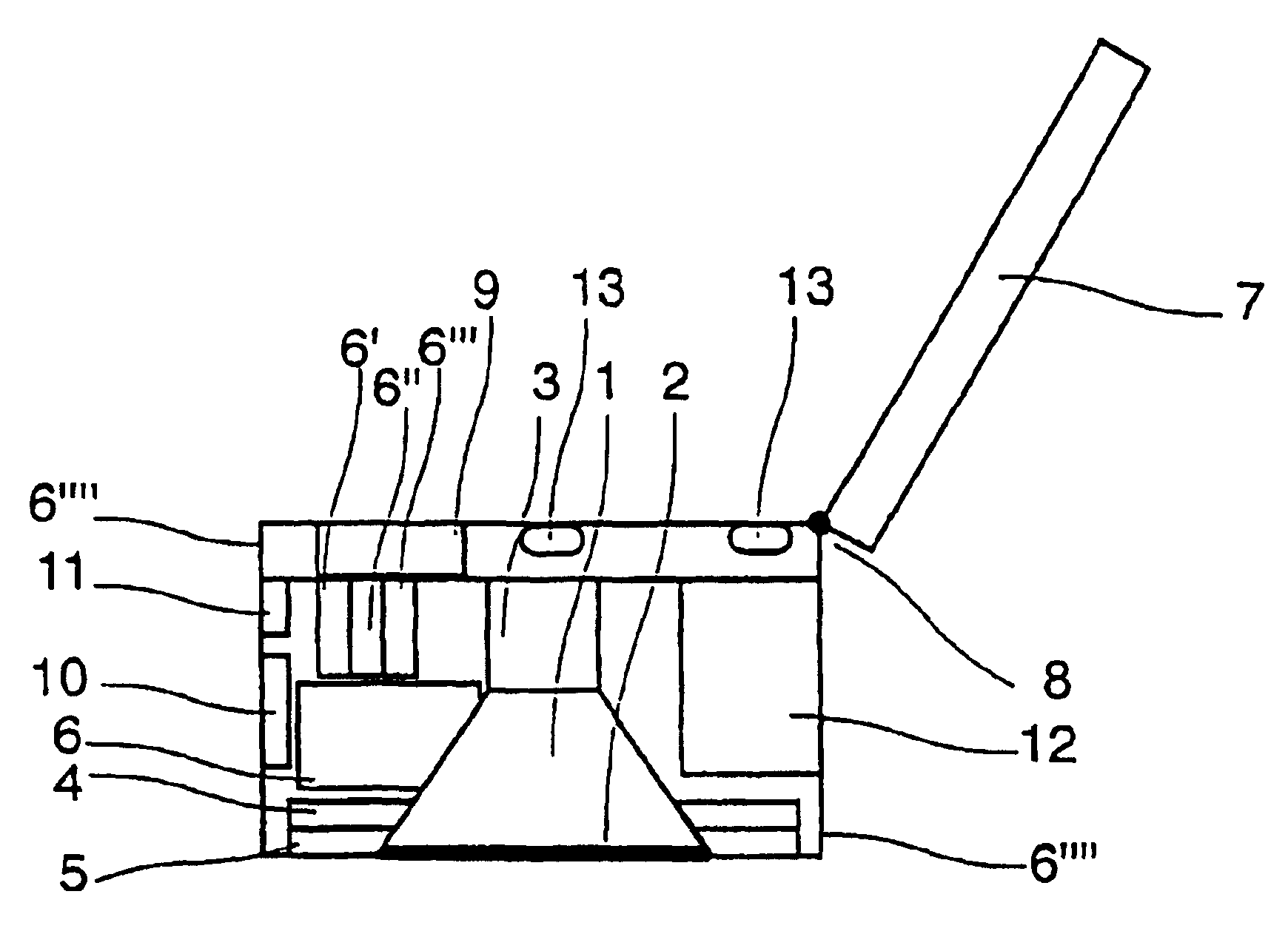
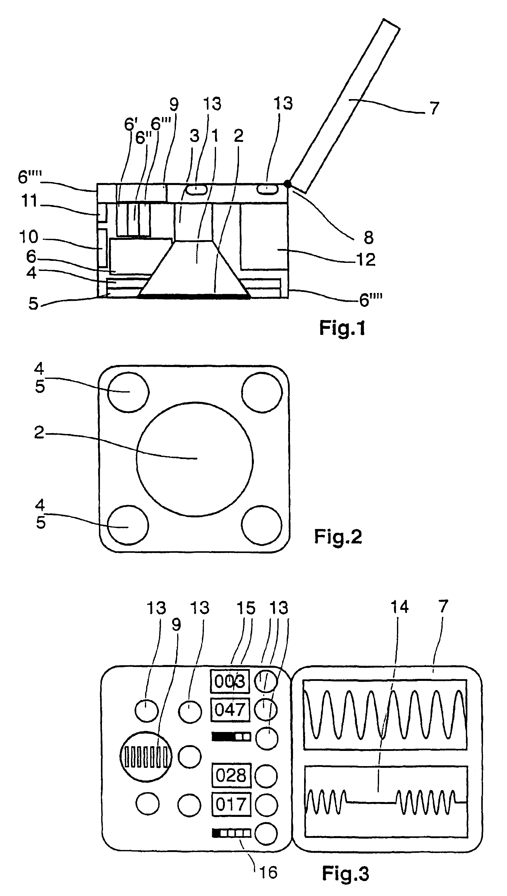
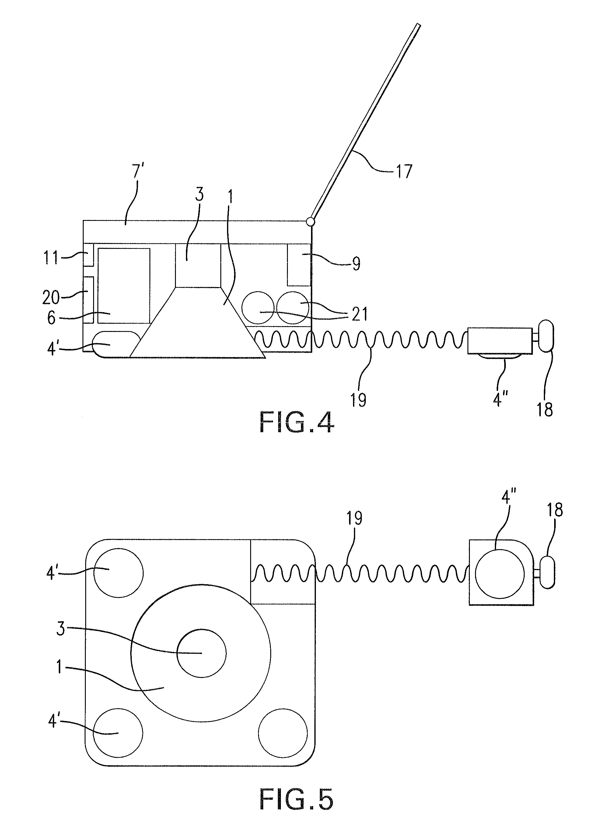
[0022]In the described version of the Diagnostic Device in FIG. 1 to 3, are the recording units for the acoustic signals of the body (1, 2, 3) as well as the recording units for the electrical signals, in the form of tension fluctuations and / or of impedance measurements, and / or for temperature measurements, consisting of four measuring electrodes (4) with a receptacle for contact gel (5), placed in the casing; the sound funnel and the measuring electrodes with the contact gel receptacle are pointed towards the person / object being examined, when using the device. The membrane (2) of the sound funnel and the cover for the contact gel receptacle (5) of the measuring electrode (4), are positioned on a horizontal level. On the upper side of the device, is the operational and display area with the operational keys (13), the speaker (9), the digital display areas (15) and the amplitude beam display (16). On the outer rim of the casing of the Diagnostic Device, is a foldable monitor / screen ...


PUM


Abstract

The invention lies in the domain of medical technology and relates to a diagnosis and monitoring device for the rapid diagnosis and monitoring of vital parameters of the human or animal body, in particular of the heart and/or lungs, said device being compact, without cables and/or tubes and easy to use for the user. Devices such as a bell (1) comprising a membrane (2) and/or measuring electrodes (4, 5) for receiving and forwarding acoustic and/or electric signals of the body are arranged in a housing with a cross-section that is approximately the size of the palm of a hand and a height of approximately half a hand-width, on the side of a housing that is to be placed on the body. Said devices are connected to a device in the housing, which analyses, filters and stores the signals of the receiving device and to additional devices for visually reproducing the evaluated signals in digital or analogue form using display fields (14, 15, 16, 17) and/or for acoustically reproducing said signals using a loudspeaker (9) located in the housing. The diagnosis and monitoring device also comprises interfaces (10, 11) for connecting external devices and equipment (e.g. computer, earphones, printer). The principal characteristics of the invention are illustrated in FIGS. 1 and 3.

Description

BACKGROUND OF THE INVENTION[0001]This invention is a device for the examination and monitoring of vital parameters of the human or animal body, in the form of a compact Diagnostic Device, which may be used single-handedly and within easy reach, without the necessity for cables or tubes.[0002]With already known examination and monitoring equipment, several electrodes are attached to the body to be examined, to measure electrical tension fluctuations of the body. Usually, the number of electrodes is increased proportionally to the number of measuring vectors. With most of the well-known equipment, these electrodes are, connected by means of cables to the amplifier units in order to amplify the signals and connect them to separate analysis equipment. This well-known examination and monitoring equipment is, through the cable connections mentioned above and the separate amplifier units and the analysis equipment and especially through the dimensions of these components, most disadvantage...

Claims


Application Information

Patent Timeline
IPC IPC(8): A61B5/103A61B5/00A61B5/022A61B5/145A61B5/1455A61B5/332A61B7/04
CPCA61B5/01A61B5/0404A61B9/00A61B5/053A61B7/04A61B5/044A61B5/332A61B5/339
Inventor RAHE-MEYER, NIELS
Owner SUPER SHINE VENTURES LTD
Why Eureka
Try Eureka