Automatic analyzer

a technology of automatic analysis and analyzer, applied in the direction of mechanical vibration separation, process and machine control, instruments, etc., can solve the problems of affecting the result of the next analysis, reducing measuring accuracy, and not being effective as agitating means, and achieve high-reliability analysis results

Inactive Publication Date: 2011-06-07
HITACHI LTD
View PDF34 Cites 4 Cited by
  • Summary
  • Abstract
  • Description
  • Claims
  • Application Information

AI Technical Summary

Benefits of technology

[0013]The object of the present invention is to provide an automatic analyzer which is capable of effective agitation of the reagent and specimen, in a case to be difficult to insert the agitation rod because of a small capacity of the reaction vessel, by a method to agitate the reagent and specimen without touching thereto and without carry-over between specimens or water brought into the next process, thereby ensuring highly reliable results of analysis.

Problems solved by technology

When this conventional automatic analyzer is used, a trace amount of chemicals or specimens deposited on the agitating rod will cause a phenomenon called carry-over which affects the result of the next analysis.
This is not effective as an agitating means to promote mixing between reagent and specimen.
This will result in reduced measuring accuracy.
However, it becomes difficult to physically insert and to reciprocate the agitating rod due to reduced capacity of the reaction vessel in case of the automatic analyzer using the reaction vessel having a reduced capacity, where the agitating rod having a spatula-shaped tip in the agitator to mix the reagent with the specimen is inserted into said reaction vessel to rotate the agitating rod or move it in reciprocating motion.
Furthermore, even if the agitating rod is cleaned, it is impossible to completely eliminate the phenomenon of carry-over where a trace amount of specimen or reagent is carried over to the next analysis.
It is also impossible to eliminate the possibility of water for cleaning being brought into the reaction vessel by the agitating rod.
Said carry-over and transfer of cleaning water into the vessel will have some adverse effect on the result of analysis when the capacity of the reaction vessel is reduced and the quality of reagent and specimen is decreased.

Method used


Image

  • Automatic analyzer
  • Automatic analyzer
  • Automatic analyzer

Examples


first embodiment

[0061]Using FIGS. 1 to 4, the following describes the first embodiment of the automatic analyzer according to the present invention:

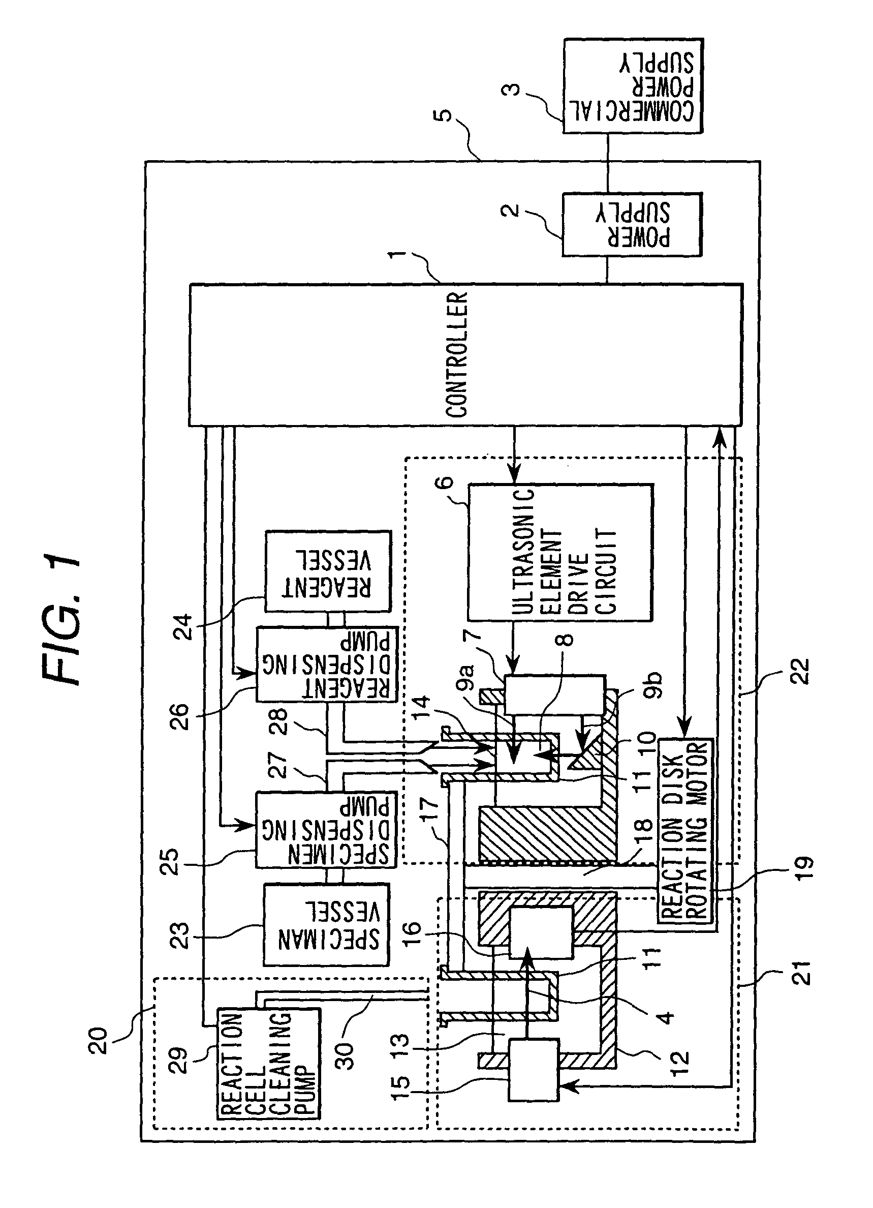
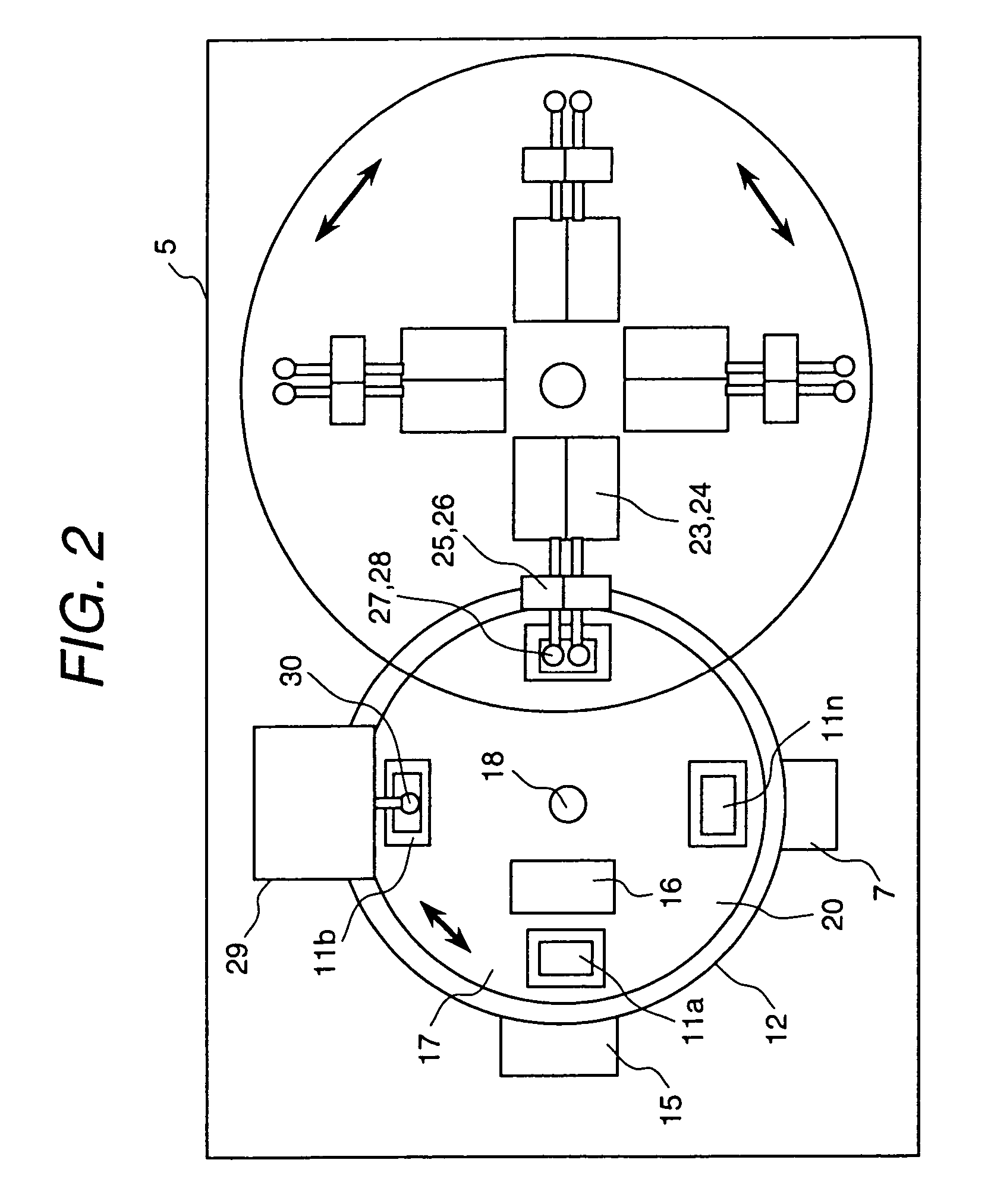
[0062]FIG. 1 is a schematic cross sectional view representing a part of the automatic analyzer according to the present invention. FIG. 2 is a partial plan representing the analyzer of FIG. 1. FIG. 3 is a schematic cross sectional view representing of the major portion related to the first embodiment according to the present invention.

[0063]Controller 1 in FIGS. 1 and 2 comprises an information processing system or sequencer provided with a CPU, memory and I / O. Using the automatic analysis and diagnosis program and data stored in the memory, said controller processes or administers and controls the operation of the automatic analyzer 5 and information required for analysis operation through the CPU.

[0064]Detector 21 comprises a reaction vessel 11 to mix between reagent and specimen, a light emitting unit 15 to generate light 4 to be applied to said reac...

second embodiment

[0085]FIG. 5 is a schematic cross sectional view representing the major portion of the second Embodiment of the automatic analyzer according to the present invention. The portions other than the configuration shown in FIG. 5 are the same as those shown in the first Embodiment, so they will not be illustrated or described.

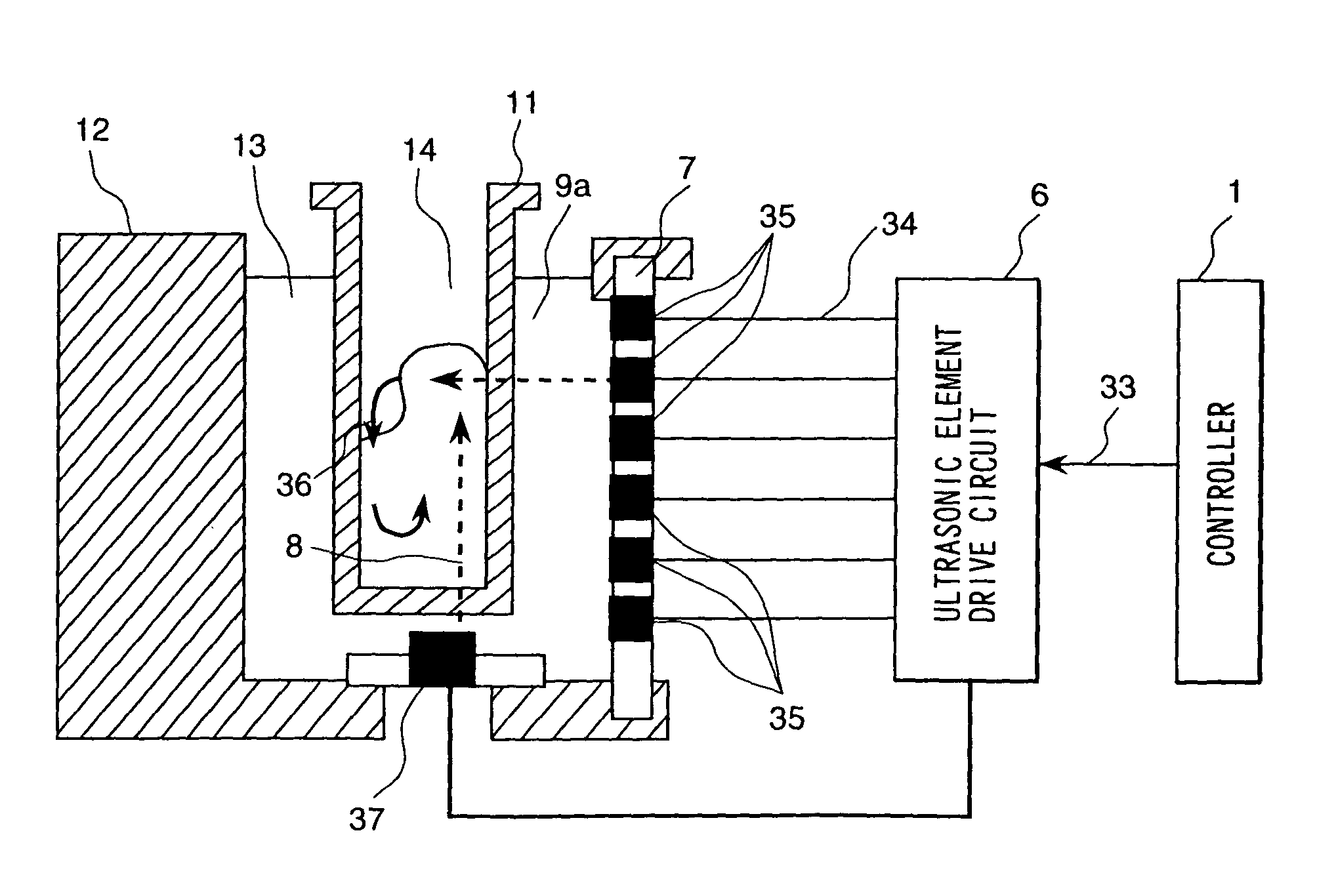
[0086]In this second Embodiment given in FIG. 5, the bottom of the position corresponding to the agitator 22 is designed in an inclined structure, wherein said bottom is placed face to face with the bottom 8 of the reaction vessel 11 of the heat insulating bath 12. The ultrasonic reflecting mechanism 10 is designed to ensure that the lateral ultrasonic wave 9b generated by the piezoelectric element 35 is reflected to proceed along the side wall side wall close to piezoelectric element 35) of this reaction vessel 11 from the bottom of the reaction vessel 8. This allows the lateral ultrasonic wave 9b to proceed in the upward direction so that it can be used as the low...

third embodiment

[0091]FIG. 6 is a schematic cross sectional view representing the major part of the automatic analyzer according to the third Embodiment of the present invention. The portions other than the configuration shown in FIG. 6 are the same as those shown in the first Embodiment, so they will not be illustrated or described.

[0092]The bottom inside the reaction vessel 11 of the automatic analyzer in FIG. 6 is designed in an inclined structure to create the mechanism which ensures that lateral ultrasonic wave 9b generated by the piezoelectric element 35 is reflected to proceed to the liquid level from the bottom of the reaction vessel 11. This allows the lateral ultrasonic wave 9b to proceed upward; thus, it can be used as lower ultrasonic wave 8.

[0093]The sequence to actuate ultrasonic wave generation actuates the piezoelectric element for lateral irradiation 35 located at the bottom to generate lateral ultrasonic wave 9b. Lateral ultrasonic wave 9b enters the reaction vessel 11 from the si...


PUM

PropertyMeasurementUnit
physical propertiesaaaaaaaaaa
physical propertyaaaaaaaaaa
mechanical oscillationaaaaaaaaaa

Abstract

Multiple piezoelectric elements 35 are arranged in a row along the top of liquid level in the reaction vessel 11. An ultrasonic reflecting material 38 is installed on the bottom of the portion of the heat insulating bath 12 where heat insulating medium 13 is stored. A lateral ultrasonic wave 9b is generated on the lower side is generated by actuation of the piezoelectric element 35. Wave 9b is reflected by the ultrasonic reflecting material 38. As a lower ultrasonic wave 8 advances along the wall surface of the reaction vessel, it collides with the specimen liquid level, thereby causing a portion of the liquid level closer to the piezoelectric element 35 to be raised. When the lateral ultrasonic wave 9a is applied to this portion, it reaches the inclined portion of the raised liquid level of the specimen. Swirling flow by agitation 36 is produced by the acoustic radiation pressure of the ultrasonic wave. The specimen and reagent are mixed and agitated by this swirling flow.

Description

[0001]This is a divisional of application U.S. Ser. No. 09 / 789,625, filed Feb. 22, 2001, now U.S. Pat. No. 6,737,021.BACKGROUND OF THE INVENTION[0002]The resent invention relates to the automatic analyzer which uses reagent or the like to analyze the components of the specimen as objects of analysis, and particularly to the automatic analyzer provided with an agitator to ensure that reagent required for analysis of specimen components is mixed with the specimen.[0003]To mix reagent with the specimen in the agitator of the conventional automatic analyzer, an agitating rod 61 having a spatula-shaped tip is inserted into the reaction vessel where reagent is mixed with the specimen, and the agitating rod is rotated or moved in reciprocating motion.[0004]For example, the agitating rod 61 having a spatula-shaped tip is inserted into the reaction vessel 11 containing a mixture of reagent and specimen as shown in FIG. 9(a), and the agitating rod 61 is rotated by an actuator 60. Or the agita...

Claims


Application Information

Patent Timeline
Patent Type & Authority Patents(United States)
IPC IPC(8): G01N15/06B06B1/00B01F11/02G01N35/00G01N35/02
CPCB01F11/0283G01N35/025Y10T436/11G01N2035/00554B01F31/87
Inventor WATARI, SHIGENORIKATOU, HAJIMEKAMBARA, KATSUHIROUCHIDA, HIROYASUSHIBUYA, TAKESHI
Owner HITACHI LTD
Why Eureka
Try Eureka