Method for reading out signal charges from an image sensor having different exposure times

a signal charge and image sensor technology, applied in the field of image sensors, can solve the problems of difficult to achieve clear image depiction of images (objects), limited incident light quantity of these area sensors, etc., and achieve the effect of expanding the dynamic range and suppressing the deterioration of picture quality

Inactive Publication Date: 2011-06-07
COLLABO INNOVATIONS INC
View PDF14 Cites 7 Cited by
  • Summary
  • Abstract
  • Description
  • Claims
  • Application Information

AI Technical Summary

Benefits of technology

[0015]According to the present invention, the exposure time is varied through a line unit. Therefore, even in the case of photographing a dynamic picture to pick up an object under movement, it is possible to suppress deterioration generated in the picture quality such as blur in the image, while achieving expansion of the dynamic range.

Problems solved by technology

The effective incident light quantity of these area sensors is limited to a narrow area.
As described, the dynamic range is narrow when one of those signals is employed alone, and it is difficult to achieve clear image depiction of the image (object) with a significant difference between the light and shade (high contrast), which has the areas A, B, and C mixed in the same image.

Method used


Image

  • Method for reading out signal charges from an image sensor having different exposure times
  • Method for reading out signal charges from an image sensor having different exposure times
  • Method for reading out signal charges from an image sensor having different exposure times

Examples


first embodiment

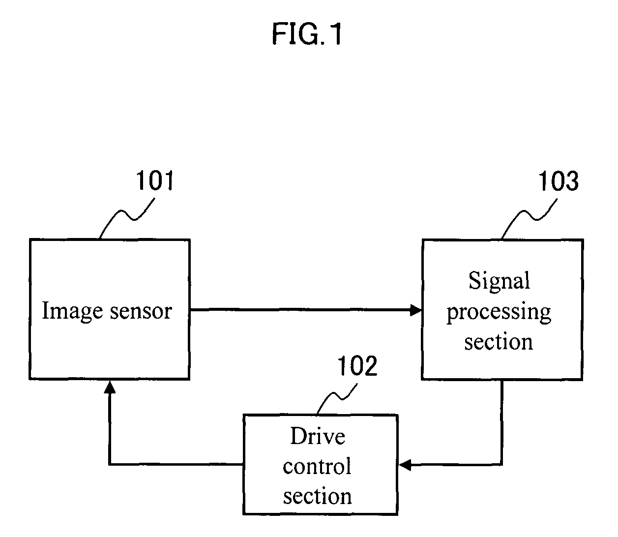
[0077]FIG. 1 is a schematic diagram of a solid-state image pickup device that comprises an MOS image sensor according to a first embodiment of the present invention. The solid-state image pickup device comprises an MOS image sensor 101, a drive control section 102 for drive-controlling the image sensor 101, and a signal processing section 103 for processing the signal from the image sensor 101.

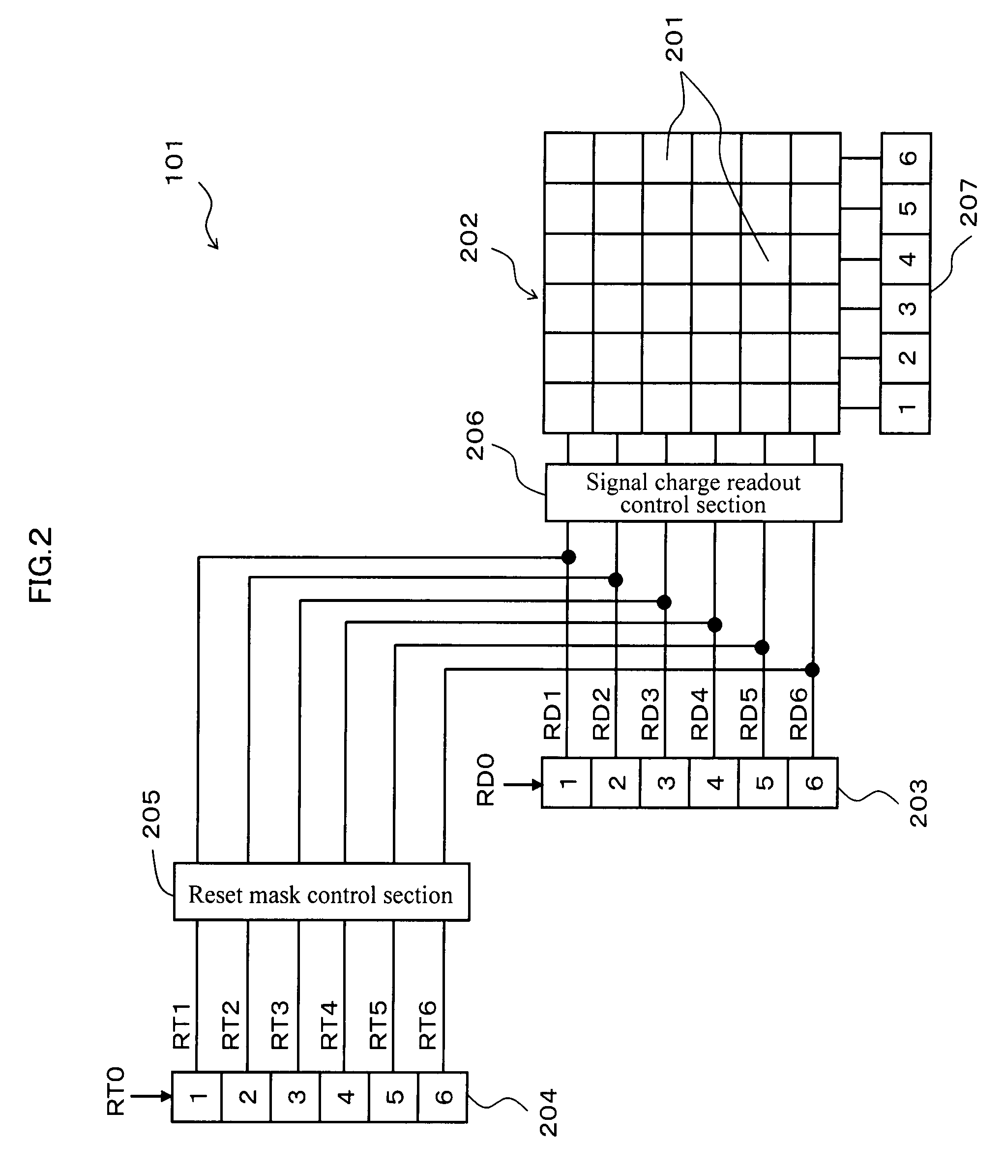
[0078]FIG. 2 is a block diagram showing the detailed structure of the image sensor 101. In FIG. 2, reference numeral 201 indicates an image pickup element, and 202 is an area sensor. Reference numeral 203 is a vertical shift register that functions as a vertical control section, and 204 is a reset shift register that functions as a reset control section. Reference numeral 205 is a reset mask control section, 206 is a signal charge readout control section, and 207 is a horizontal shift register. The vertical shift register 203, the reset shift register 204, the reset mask control section 205, a...

second embodiment

[0116]FIG. 6A shows Bayer-type color filter array 210. The Bayer-type color filter array 210 is an example of a filter array that corresponds to the color filters based on three primary colors of the light (red, green, blue). In the Bayer-type color filter array 210, G pixel that is the main signal of the luminance signal requiring high resolution is indicated as pixel Gr and pixel Gb, and these pixels Gr and Gb are arranged alternately in the pixel array area of lattice pattern while providing a space of one pixel between them. Then, pixel R and pixel B are arranged alternately in those spaces.

[0117]In the Bayer-type color filter array 210, four pixels (2×2) of pixel Gr, pixel Gb, pixel R, and pixel B constitute a base unit. In the area sensor 202 having the Bayer-type color filter arrays 210, the color filter arrays 210 are arranged in an orderly manner.

[0118]As shown in FIG. 6B, in an exposure area 211 of the area sensor 202, there are set the first line pair consisting of the od...

third embodiment

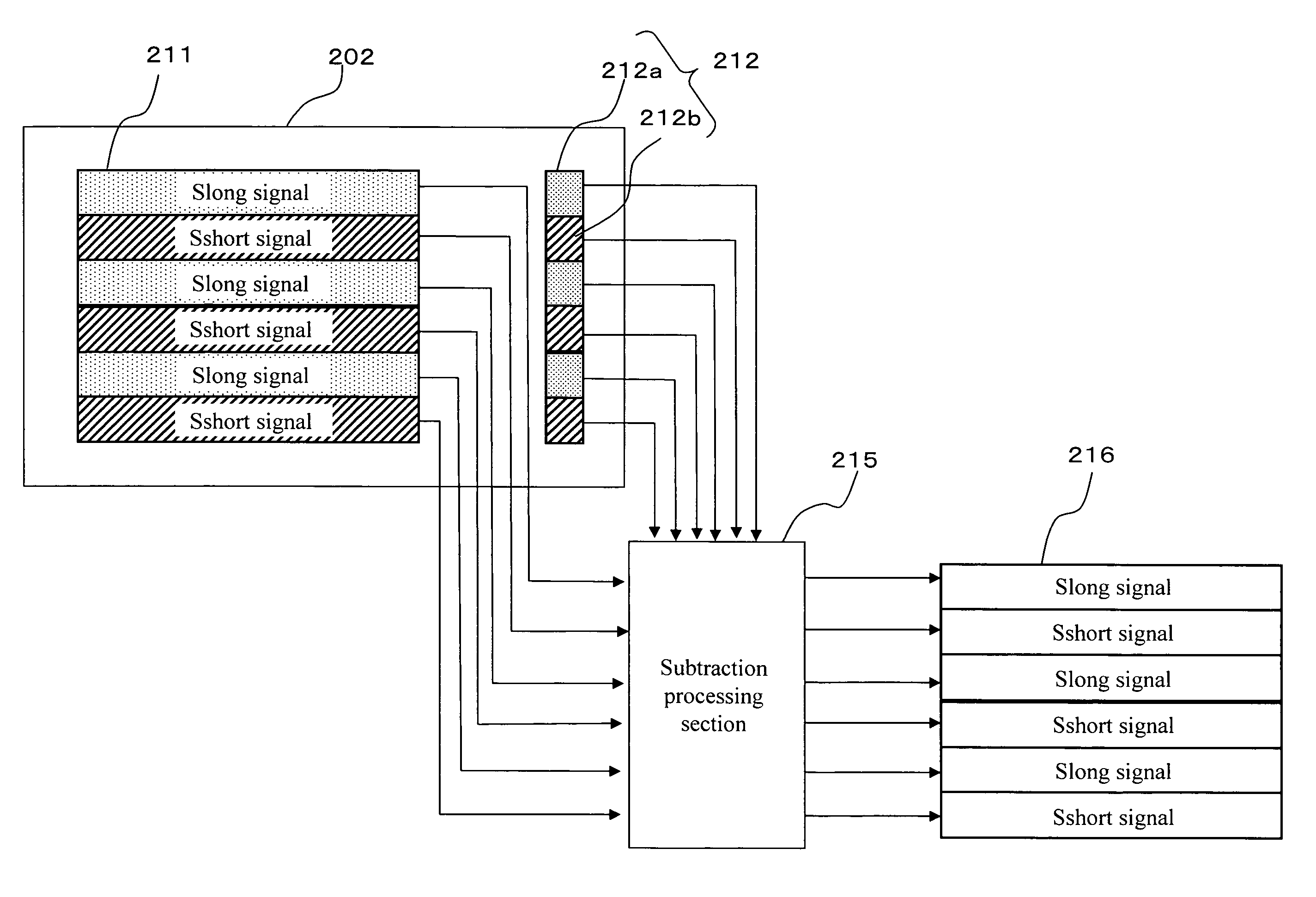
[0129]A third embodiment of the present invention will be described referring to FIG. 8. The third embodiment is distinctive in terms of the processing of a subtraction processor 215. The long exposure signal Slong is supplied to the subtraction processor 215 from an OB pixel section 212a located on the first line pair. Further, the short exposure signal Sshort is supplied to the subtraction processor 215 from an OB pixel section 212b located on the second line pair. The long exposure signal Slong and the short exposure signal Sshort are supplied separately to the subtraction processing section 215.

[0130]The subtraction processing section 215 separately processes the output signals (the long exposure signal Slong, the short exposure signal Sshort) of the OB pixel sections 212a and 212b. That is, the subtraction processing section 215 separately and individually samples the output signals of each of the OB pixel sections 212a, 212b to generate the OB components that respectively corr...


PUM


Abstract

Suppress deterioration in picture qualities while achieving expansion in a dynamic range.An image sensor readout method that reads out, from an area sensor where a plurality of image pickup elements are arranged in matrix, signal charges that are accumulated in the image pickup elements is constituted as follows. First, plural kinds of exposure time different in length from each other are set, and the exposure time is then individually allocated to each line of the area sensor. Next, the signal charges accumulated in the image pickup elements in the allocated exposure time are read out through a line unit of the area sensor. Then, the read out signal charges are synthesized through a screen unit of the area sensor.

Description

RELATED APPLICATIONS[0001]This application is the U.S. National Phase under 35 U.S.C. §371 of International Application No. PCT / JP2005 / 019889 filed on Oct. 28, 2005, which in turn claims the benefit of Japanese Application No. 2004-319148, filed on Nov. 2, 2004, the disclosures of which Applications are incorporated by reference herein.TECHNICAL FIELD[0002]The present invention relates to an image sensor, in particular, to an exposure time control technique for achieving wide dynamic range photographing which can finely capture image information of both bright part and dark part of an object that has both the bright part and the dark part.BACKGROUND ART[0003]A solid-state image pickup device for performing digital-processing on image data, e.g. a digital still camera that handles still picture, and a digital video camera that handles a dynamic picture, performs photoelectric-conversion on an optical image obtained through an image pickup optical system by a photoelectric conversion ...

Claims


Application Information

Patent Timeline
Patent Type & Authority Patents(United States)
IPC IPC(8): H04N5/235G03B7/00H04N5/353H04N5/355H04N5/361H04N5/369H04N5/374
CPCH04N5/2353H04N5/2355H04N5/3535H04N9/045H04N5/35581H04N5/361H04N5/374H04N5/35554H04N23/73H04N23/741H04N25/533H04N25/583H04N25/589H04N25/63H04N25/76H04N23/84H04N25/134
Inventor OGAWA, MASAHIROIMAMURA, KUNIHIRONISHIKAWA, MAYUHATANO, TOSHINOBU
Owner COLLABO INNOVATIONS INC
Why Eureka
Try Eureka