Partial coalescing of transmit buffers

a buffer and transmit buffer technology, applied in the field of network devices and systems, can solve the problems of performance and performance also suffering

Active Publication Date: 2011-06-07
ADVANCED MICRO DEVICES INC
View PDF10 Cites 23 Cited by
  • Summary
  • Abstract
  • Description
  • Claims
  • Application Information

AI Technical Summary

Problems solved by technology

When a small amount of data is scattered in several buffers, performance can suffer when the network device obtains the data stored within the

Method used


Image

  • Partial coalescing of transmit buffers
  • Partial coalescing of transmit buffers
  • Partial coalescing of transmit buffers

Examples


Embodiment Construction

The present invention will now be described with respect to the accompanying drawings in which like numbered elements represent like parts. The figures provided herewith and the accompanying description of the figures are merely provided for illustrative purposes. One of ordinary skill in the art should realize, based on the instant description, other implementations and methods for fabricating the devices and structures illustrated in the figures and in the following description, and such alternatives are contemplated as falling within the scope of the present invention.

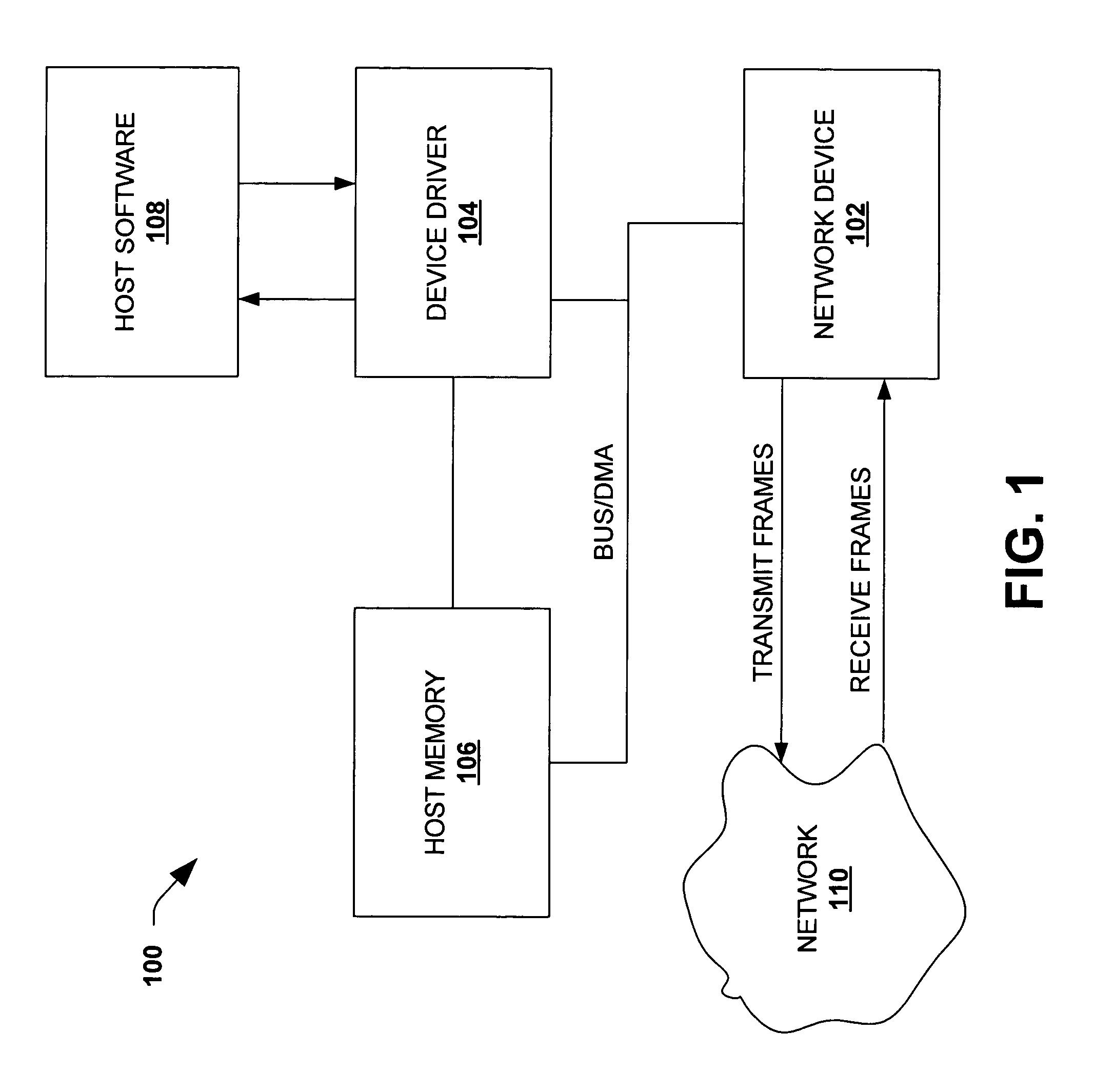
Many network devices / controllers at least partially function as busmasters in that they have a built in direct memory access (DMA) engine that allows them to obtain data from system memory without substantial intervention or involvement by a host processor. This requires that a network device driver provide physical addresses of the buffers within system memory that hold the data to the network device. However, when...


PUM


Abstract

The present invention facilitates overall system performance by balancing system resource utilization and network throughput. The invention analyzes packets received from host software selects one or more of buffers to coalesce into a single, coalesced buffer. The selection is based upon an initial fragment size selected to facilitate overall system performance. The coalesced buffer and non-coalesced buffers, are passed to a network device for transmission.

Description

FIELD OF THE INVENTIONThe present invention relates generally to network devices and systems, and more particularly, to systems and methods for coalescing transmit buffers.BACKGROUND OF THE INVENTIONHost-computing systems, such as personal computers, are often operated as nodes on a communications network, where each node is capable of receiving data from the network and transmitting data to the network. Data is transferred over a network in groups or segments, wherein the organization and segmentation of data are dictated by a network operating system protocol, and many different protocols exist. In fact, data segments that correspond to different protocols can co-exist on the same communications network. In order for a node to receive and transmit information packets, the node is equipped with a peripheral network interface device, which is responsible for transferring information between the communications network and the host system. For transmission, a processor unit in the hos...

Claims


Application Information

Patent Timeline
IPC IPC(8): G06F15/16G06F12/00
CPCH04L49/9057
Inventor KARIGHATTAM, KISHOREPADIYAR, PRASAD P.VASUDEVA, HARISH
Owner ADVANCED MICRO DEVICES INC
Why Eureka
Try Eureka