Lung simulator

a simulator and lungs technology, applied in the field of lungs simulators, can solve the problems of severe respiratory distress, increased cost, and explosion of health care costs, and achieve the effects of avoiding expense, ensuring co2 flow predictability, and eliminating time-consuming

Active Publication Date: 2011-06-14
INGMAR MEDICAL
View PDF3 Cites 25 Cited by
  • Summary
  • Abstract
  • Description
  • Claims
  • Application Information

AI Technical Summary

Benefits of technology

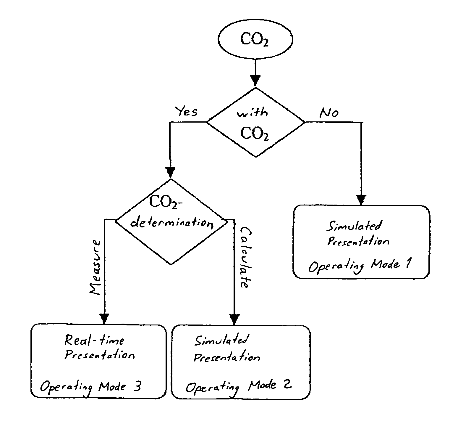
[0049]In a second embodiment, the present invention saves the expense for a capnography system as part of the respiratory simulator. The resulting EtCO2 values are, as opposed to the measured values in the first embodiment, calculated and predicted from data available from the simulator (e.g., tidal volumes, breathing frequency, etc.). This CO2 delivery system uses a regulated valve design (i.e., pressure drop from a known input pressure controlled with a feedback loop, allowing flow via a precision orifice). This design generally ensures the predictability of CO2 flow necessary for calculation of EtCO2 without actual measurement thereof. The use of a regulated valve also eliminates the time consuming and, therefore, costly step of accurately mapping the response of each proportional metering valve being used in eac

Problems solved by technology

In recent years, the demographic trend of industrial countries has led to an explosion of health-care costs.
A comparison between the trend of health-care costs and the aging of the population shows that a large percentage of this cost increase results from hospital stays by elderly people.
A change in the gas mixture such as, for example, an increase of the CO2 content by 5%, would result in severe respiratory distress.
The measurement presents problems in actual practice, because the respiratory musculature has to be disregarded for this purpose.
An increasing CO2 production always results in an increasing O2 consumpt

Method used


Image

  • Lung simulator
  • Lung simulator
  • Lung simulator

Examples


Embodiment Construction

[0076]For purposes of the description hereinafter, spatial or directional terms shall relate to the invention as it is oriented in the drawing figures. However, it is to be understood that the invention may assume various alternative variations, except where expressly specified to the contrary. It is also to be understood that the specific apparatus illustrated in the attached drawings, and described in the following specification, are simply exemplary embodiments of the invention. Hence, specific dimensions and other physical characteristics related to the embodiments disclosed herein are not to be considered as limiting.

[0077]In a desirable embodiment, the present invention is implemented in connection with an existing lung simulator that provides a physical representation of the equation of motion with respect to the human lung, namely, Pvent+Pmus=V×R+V×1 / C. An exemplary lung simulator for use with the present invention is the Active Servo Lung 5000 (ASL 5000), marketed by IngMar...


PUM


Abstract

A system and method of delivering CO2 in a respiration closed-loop control system to a respiratory simulator includes (a) providing a CO2 supply to a respiratory simulator having a piston/cylinder arrangement; (b) providing flow control hardware between the CO2 supply and the piston/cylinder arrangement; (c) generating a first control signal representative of a predefined amount of CO2; and (d) providing the predefined amount of CO2 into the piston/cylinder arrangement. Thereafter, either (i) an end-tidal carbon dioxide partial pressure (EtCO2) value is determined based on an amount of CO2 emptied from the piston/cylinder arrangement during an exhalation phase of the respiratory simulator or (ii) an EtCO2 value is calculated via an equation. A second control signal is generated that is representative of a tidal volume and a breathing frequency representative of a physiological response to the EtCO2 value to effect corresponding movement of the piston in a next inhalation and exhalation phase.

Description

CROSS REFERENCE TO RELATED APPLICATIONS[0001]This application claims the benefit of U.S. Provisional Patent Application No. 60 / 716,135, filed Sep. 12, 2005, and entitled “Lung Simulator,” the contents of which are incorporated herein by reference.BACKGROUND OF THE INVENTION[0002]1. Field of the Invention[0003]The present invention relates to a lung simulator and, more specifically, to a system for simulating lung performance more realistically by accounting for a hypothetical patient's response to a physiological CO2 partial pressure.[0004]2. Description of Related Art[0005]In recent years, the demographic trend of industrial countries has led to an explosion of health-care costs. A comparison between the trend of health-care costs and the aging of the population shows that a large percentage of this cost increase results from hospital stays by elderly people. The length of these stays can be reduced by optimum care administered in the hospital and by suitable follow-up care of the ...

Claims


Application Information

Patent Timeline
IPC IPC(8): G09B23/28
CPCG09B23/32G09B23/28
Inventor FREMBGEN, STEFANGREMME, MAIK
Owner INGMAR MEDICAL
Why Eureka
Try Eureka