Reflective-type mask
a mask and reflector technology, applied in the field of reflector masks, can solve the problems of increasing the mean reflectivity, unable to form the pattern on the wafer as designed, and unable to perform the function of the light shielding region
- Summary
- Abstract
- Description
- Claims
- Application Information
AI Technical Summary
Benefits of technology
Problems solved by technology
Method used
Image

Examples
first embodiment
[0053]A reflective-type mask including a main surface to be irradiated with exposure light of the present embodiment comprises a pattern region provided in the main surface, the pattern region comprising a multilayer reflective film configured to reflect the exposure light and a first absorber pattern provided on the multilayer reflective film, the first absorber pattern including a pattern which is configured to absorb the exposure light and corresponds to a pattern to be formed on a wafer; a light shielding region provided in the main surface and configured to prevent a region on the wafer excluding a predetermined region from being irradiated with the exposure light when the main surface is irradiated with the exposure light for transferring the first absorber pattern to the predetermined region on the wafer, the light shielding region comprising a second absorber pattern, the second absorber pattern having a lower reflectivity to the exposure light than the first absorber patter...
second embodiment
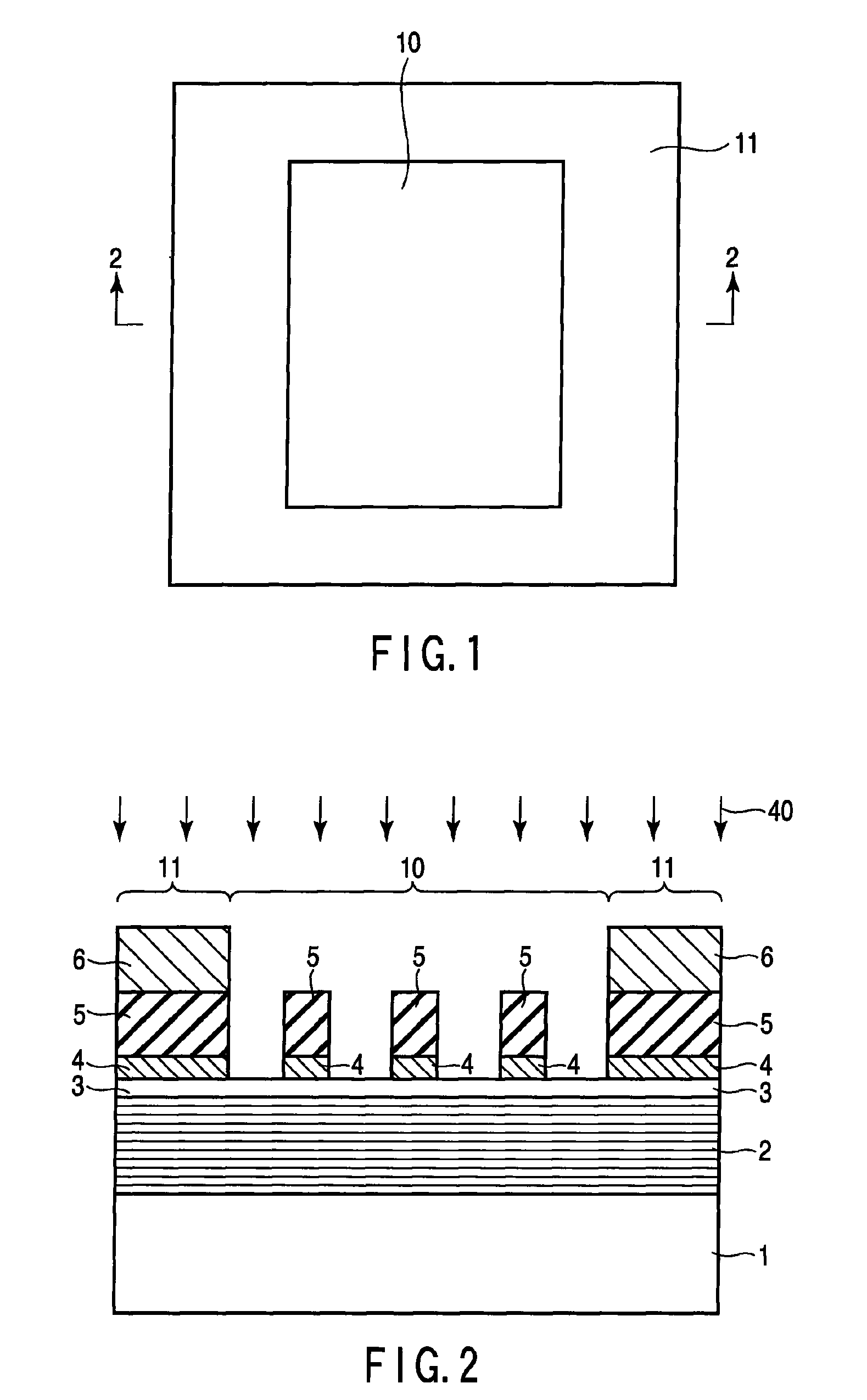
[0055]FIG. 1 is a plan view showing a reflective-type mask according to a second embodiment.
[0056]As shown in FIG. 1, the reflective-type mask comprises a region (transfer pattern region) 10 which includes a pattern corresponding to a pattern to be formed on a wafer and a region (light shielding region) 11 which is provided around the transfer pattern region 10 and absorbs the EUV light. The light shielding region 11 is a region for suppressing the leaking of light from a part where adjacent shots overlap. The reflectivity of the light shielding region 11 is, for example, less than 0.5%. Hereinafter, referring to FIG. 2, the reflective-type mask of the present embodiment will be explained further.
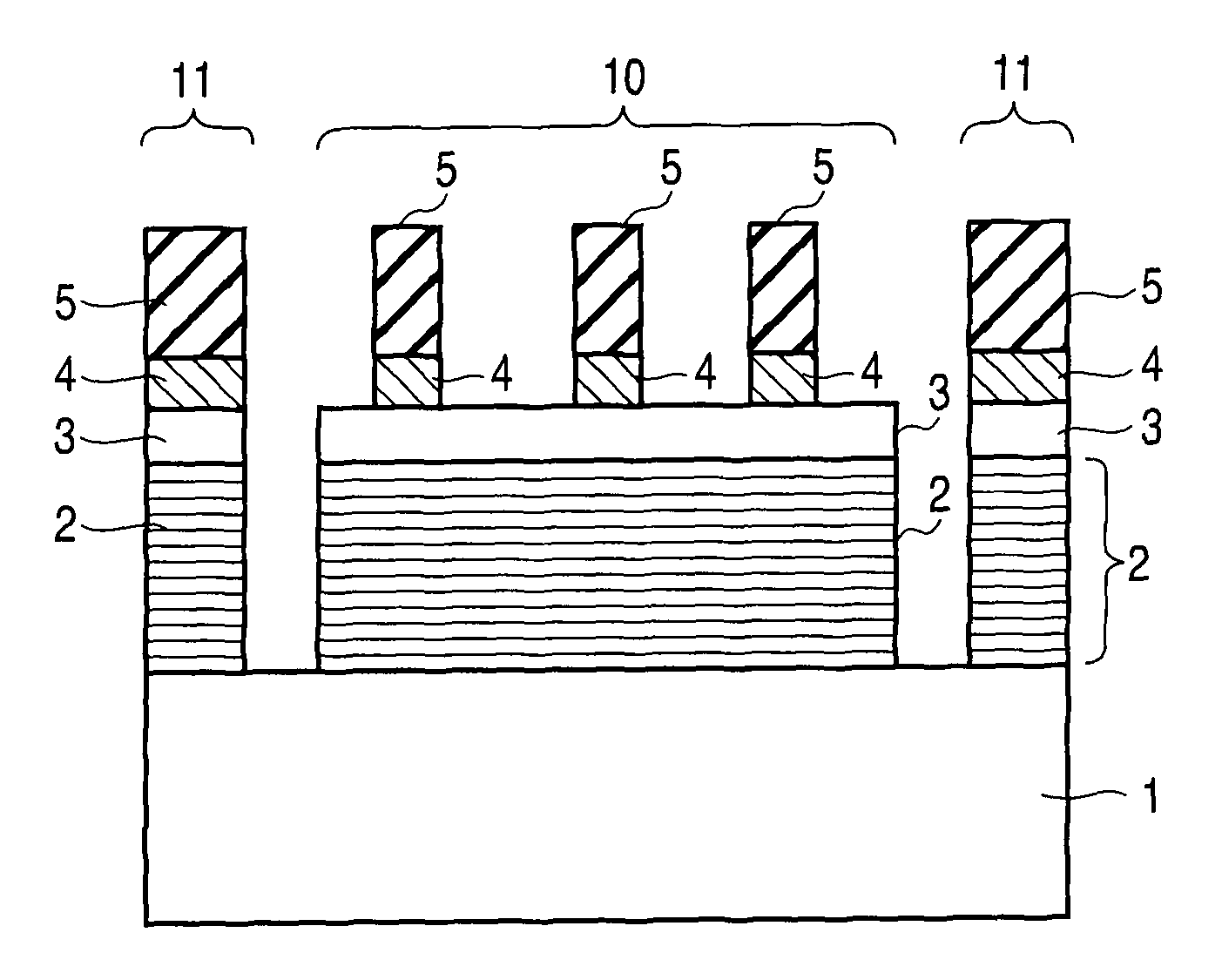
[0057]FIG. 2 is a sectional view of the reflective-type mask taken along line 2-2 of FIG. 1.
[0058]In FIG. 2, numeral 1 indicates a low expansion coefficient substrate. The low expansion coefficient substrate 1 is typically a quartz substrate in which titanium is added. On the low expansion ...
third embodiment
[0089]FIG. 14 is a plan view of a reflective-type mask according to a third embodiment. FIG. 15 is a sectional view of the reflective-type mask taken along line 14-14 of FIG. 14.
[0090]The parts corresponding to those in the above drawings are indicated by the same reference numerals and a detailed explanation of them will be omitted (hereinafter, the same holds true).
[0091]The present embodiment differs from the second embodiment in that the surface of the low expansion coefficient substrate 1 around the transfer pattern region 10 is exposed, and the exposed surface of the low expansion coefficient substrate 1 is used to suppress the leakage of the EUV light from a part where adjacent shots overlap.
[0092]The light shielding region 11 of the present embodiment includes a first light shielding region 11a provided along the periphery of transfer pattern region 10 and having a closed beltlike shape whose inner and outer circumferences are both rectangular, and a second light shielding r...
PUM
| Property | Measurement | Unit |
|---|---|---|
| thickness | aaaaa | aaaaa |
| reflectivity | aaaaa | aaaaa |
| inclination angle | aaaaa | aaaaa |
Abstract
Description
Claims
Application Information
 - R&D
- Intellectual Property
- Life Sciences
- Materials
- Tech Scout
- Unparalleled Data Quality
- Higher Quality Content
- 60% Fewer Hallucinations
Browse by: Latest US Patents, China's latest patents, Technical Efficacy Thesaurus, Application Domain, Technology Topic, Popular Technical Reports.
© 2025 PatSnap. All rights reserved.Legal|Privacy policy|Modern Slavery Act Transparency Statement|Sitemap|About US| Contact US: help@patsnap.com