Reversible electrochemical mirror for modulation of reflected radiation

a technology of reflected radiation and electrochemical mirror, which is applied in the direction of instruments, non-linear optics, optics, etc., can solve the problems of mirror reflectivity decline, and achieve the effect of efficient and precise control of reflection

Inactive Publication Date: 2000-12-26
TELEDYNE SCI & IMAGING
View PDF16 Cites 212 Cited by
  • Summary
  • Abstract
  • Description
  • Claims
  • Application Information

AI Technical Summary

Benefits of technology

The electrochemical mirror of this invention permits efficient and precise control over the reflection of visible light and other electromagnetic radiation. The mirror includes a transparent first electrode, a surface modification layer on the

Problems solved by technology

Conversely, when the polarity is reversed and a positive electrical potential is applied to the first electrode relative to the second electrode, the applied potential tends to c

Method used


Image

  • Reversible electrochemical mirror for modulation of reflected radiation
  • Reversible electrochemical mirror for modulation of reflected radiation
  • Reversible electrochemical mirror for modulation of reflected radiation

Examples


examples

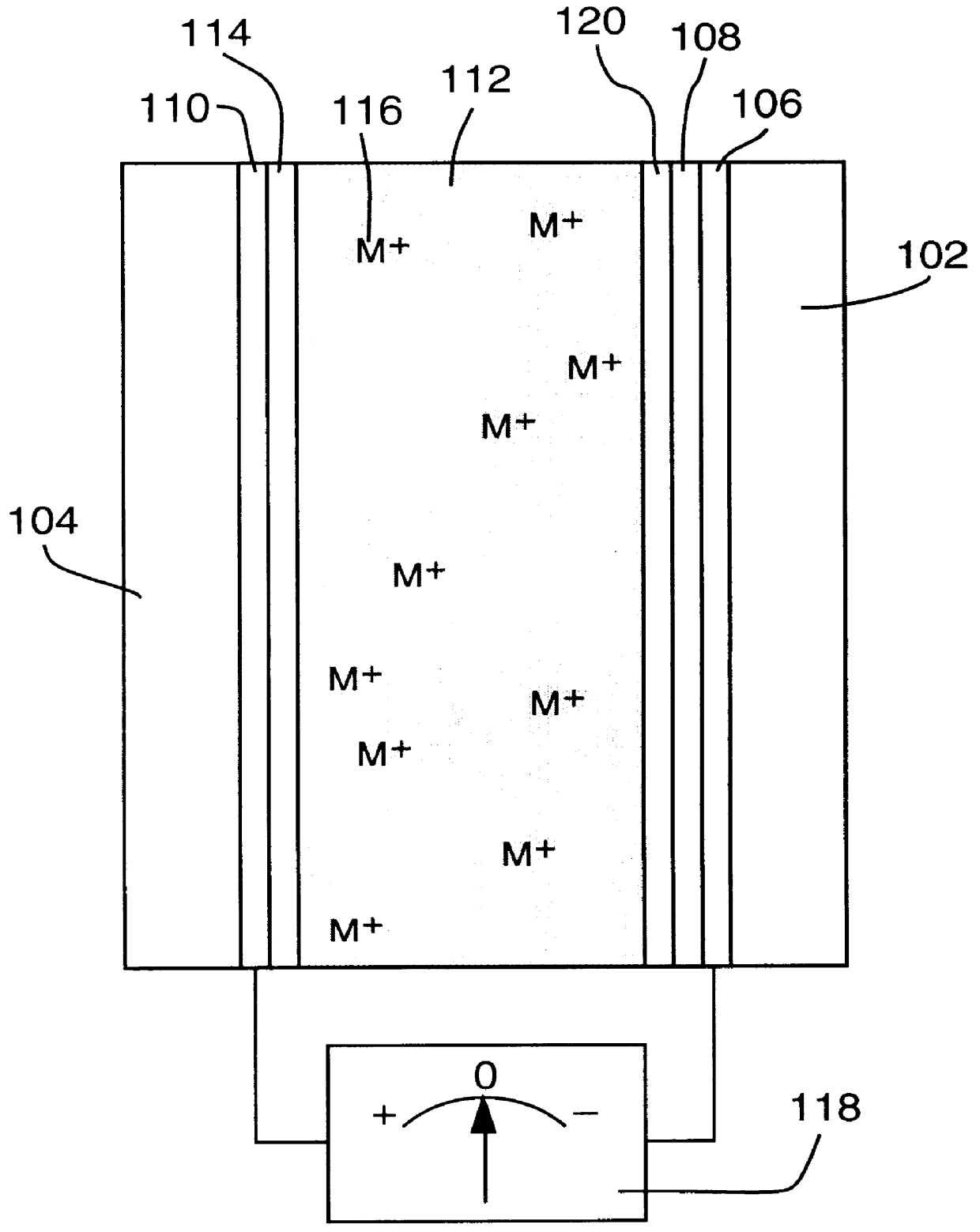
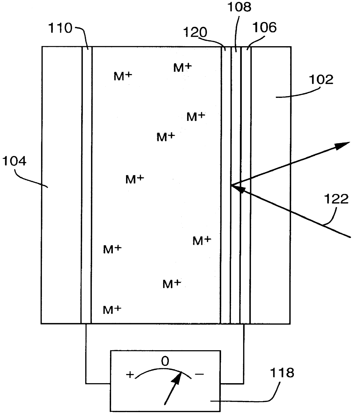
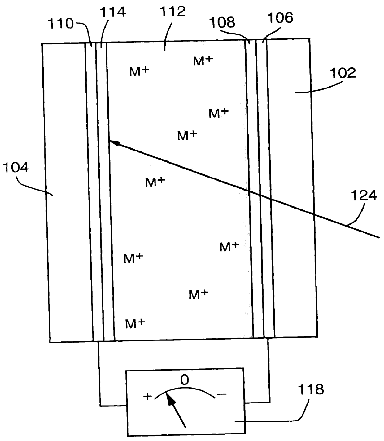
1. An adjustable reflectivity cell having a viewing area of 7.6.times.12.7 cm was constructed using a mirror electrode comprised of a 30 .ANG. sputtered platinum nucleation layer on 11 ohm / square FTO film on a glass substrate. The counter electrode was a 25 .mu.m thick silver foil (99.99% purity) that had been roughened by bead blasting (170 grit) and was mechanically supported by a thick plastic backing plate. The electrolyte was 0.15 M AgI+1.8 M LiCl in a DMSO solvent. A silicone gasket provided a seal and an electrode spacing of 2.4 mm. This cell exhibited excellent mirror formation and erasure during deep cycling between -0.5 V (relative to the mirror electrode) for 25 s and +0.25 V for 65 s for 46,000 cycles. Although mirror formation remained practically uniform, redistribution of the counter electrode silver resulting in exposure of the backing plate was eventually observed. Separate experiments showed that exclusion of oxygen from the electrolyte is necessary to avoid chemic...


PUM


Abstract

An electrochemical mirror includes a transparent first electrode and a second electrode. An electrolytic solution, disposed between the first and second electrodes, contains ions of a metal which can electrodeposit on the electrodes. A negative electrical potential applied to the first electrode causes deposited metal to be dissolved from the second electrode into the electrolytic solution and to be electrodeposited from the solution onto the first electrode, thereby affecting the reflectivity of the mirror for electromagnetic radiation. A surface modification layer applied to the first electrode ensures that the electrodeposit is substantially uniform, resulting in a mirror layer which increases the reflectivity of the mirror. A positive electrical potential applied to the first electrode causes deposited metal to be dissolved from the first electrode and electrodeposited from the solution onto the second electrode, thereby decreasing the reflectivity of the mirror.

Description

BACKGROUND OF THE INVENTIONThis invention is concerned with devices, such as mirrors and windows, having controllable transmittance and reflectivity.Sunlight transmitted through windows in buildings and transportation vehicles can generate heat (via the greenhouse effect) that creates an uncomfortable environment and increases air conditioning requirements and costs. Current approaches to providing "smart windows" with adjustable transmission for use in various sunlight conditions involve the use of light absorbing materials. These approaches are only partially effective, since the window itself is heated and because these devices, such as electrochromic devices, are relatively expensive and exhibit limited durability and cycle life. Certain liquid crystal-based window systems switch between transmissive and opaque / scattering states, but these systems require substantial voltages to maintain the transparent state. There is an important need for an inexpensive, durable low voltage sm...

Claims


Application Information

Patent Timeline
IPC IPC(8): G02F1/01G02F1/15G02F1/155G02F1/1506G02F1/153
CPCG02F1/1506G02F1/155G02F2203/02G02F2203/03
Inventor TENCH, D. MORGANWARREN, JR., LESLIE F.CUNNINGHAM, MICHAEL A.
Owner TELEDYNE SCI & IMAGING
Why Eureka
Try Eureka