

Tilt-compensated laser rangefinder
a laser rangefinder and tilt compensation technology, applied in the direction of distance measurement, instruments, using reradiation, etc., can solve the problems of not giving the user all current laser range finders on the market have a common flaw, and the user is not given the correct aiming parameters, so as to minimize the error in the measurement of the time-of-flight range and the measurement of the vertical angle.
- Summary
- Abstract
- Description
- Claims
- Application Information
AI Technical Summary
Benefits of technology
Problems solved by technology
Method used
Image

Examples
Embodiment Construction
Thus, although there have been described particular embodiments of the present invention of a new and useful Tilt Compensated Laser Range Finder, it is not intended that such references be construed as limitations upon the scope of this invention except as set forth in the following claims.
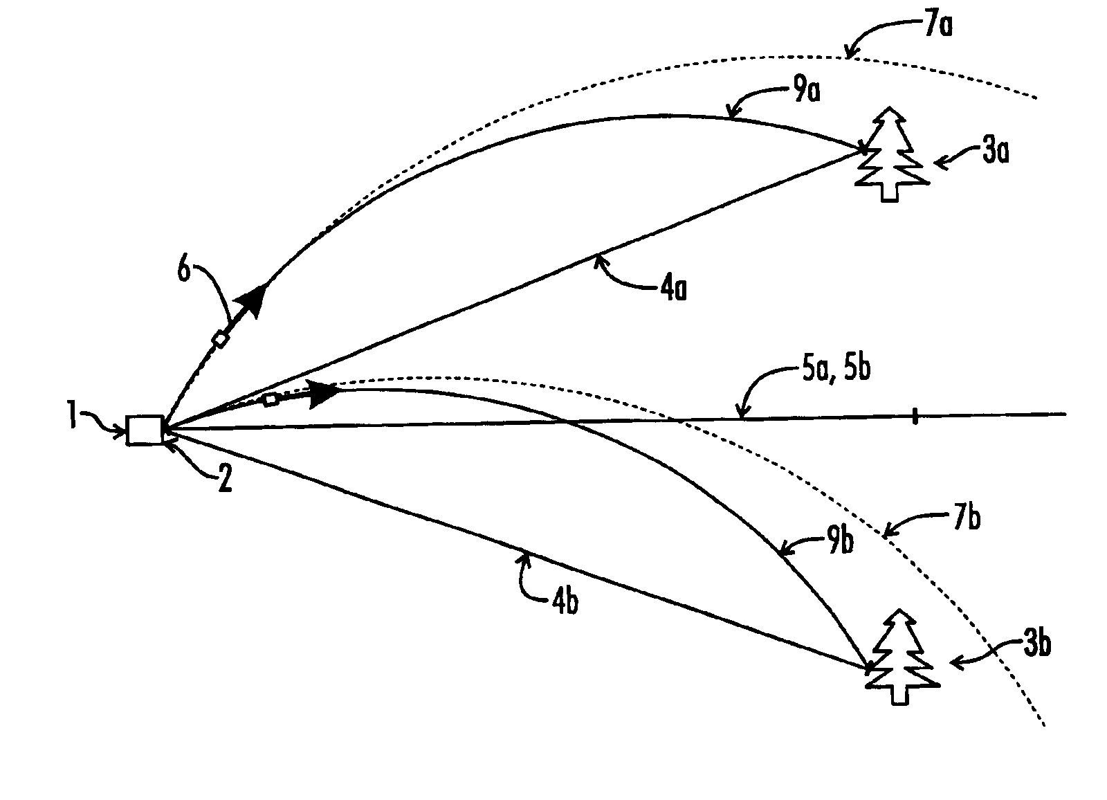
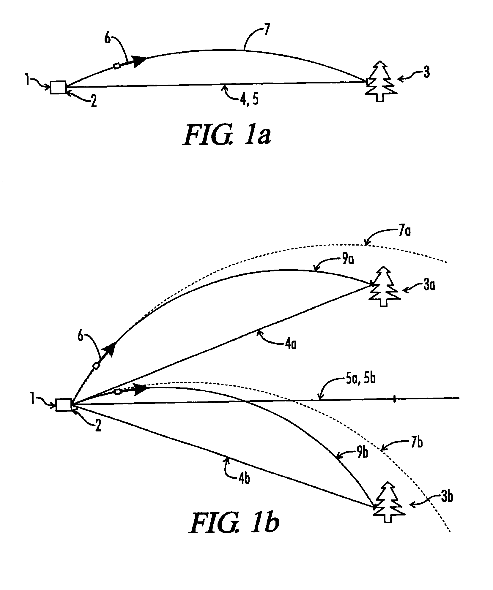
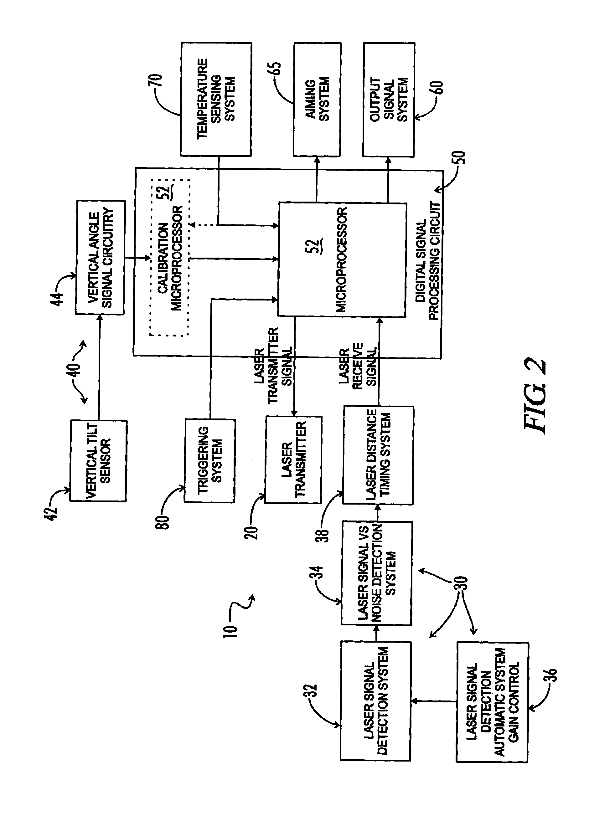
The present invention is a laser ranging device that incorporates an internal tilt sensor, an optional internal temperature sensor and an optional internal pressure sensor. The tilt sensor is used to measure the target's vertical angle relative to the horizontal reference plane. Digital signal processing circuitry controls the firing of the laser pulse, calculation of time-of-flight range, measurement of the vertical angle of the tilt sensor and storage of tilt sensor and temperature sensor calibration data. The digital signal processing circuitry then provides the user ballistic ranging information by using lookup tables and by using interpolation and extrapolation algorithms. The ballistic rangi...
PUM
 Abstract
Description
Claims
Application Information