
Circular birefringence refractometer: method and apparatus for measuring optical activity

a refractometer and circular birefringence technology, applied in the field of systems and methods for detection and measurement of circular birefringences in materials, can solve the problems of anisotropic media, insensitive scheme, relative impracticality and other problems, to achieve the effect of reducing the number of optical radiation sources

Inactive Publication Date: 2011-06-14
PRESIDENT & FELLOWS OF HARVARD COLLEGE
View PDF9 Cites 5 Cited by
  • Summary
  • Abstract
  • Description
  • Claims
  • Application Information

AI Technical Summary

Benefits of technology

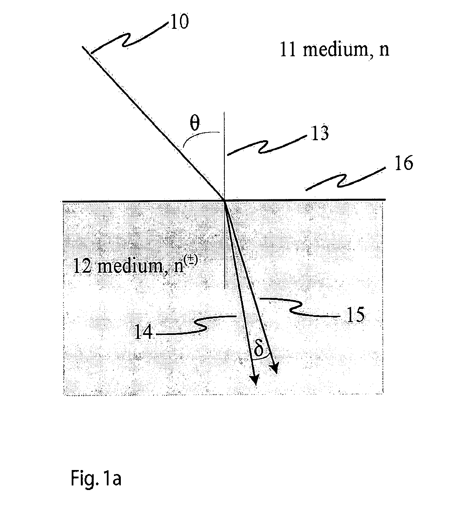
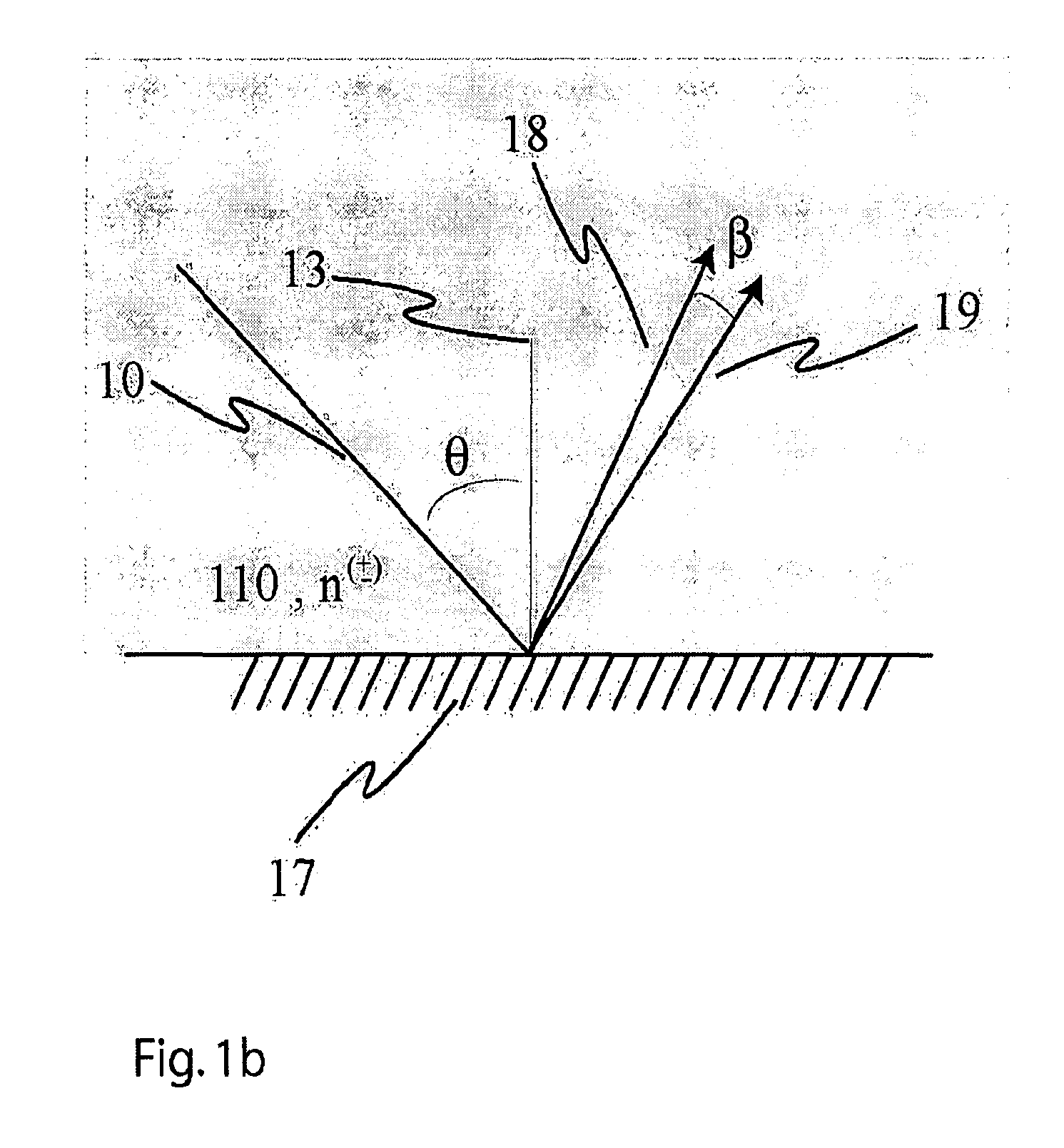
The present invention describes a method and apparatus for measuring the optical activity of a medium using the difference in the angles of refraction of left- and right-circularly polarized light. This technique can be used to determine the handedness (enantiomeric excess) of a chiral liquid or the optical purity of a solution of molecules. It is also useful for measuring optical activities in small volumes, such as liquids in capillaries or microfluidic devices. The invention is based on the separation or difference in the angles of refraction of left- and right-circularly polarized light at an interface between an optically active and an optically inactive medium. The difference in the angles of refraction causes the circularly polarized components to propagate in different directions, which can be recorded on a suitable detector. The invention is particularly useful for measuring the optical activity of small liquid volumes. The apparatus includes a container for holding the sample of the optically active medium, a light source, a means for controlling and manipulating the polarization of the light beam, and a detector.

Problems solved by technology

This, however, is a relatively impractical and insensitive scheme to measure circular birefringences.
However, these media are also anisotropic.

Method used


Image

  • Circular birefringence refractometer: method and apparatus for measuring optical activity
  • Circular birefringence refractometer: method and apparatus for measuring optical activity
  • Circular birefringence refractometer: method and apparatus for measuring optical activity

Examples


Embodiment Construction

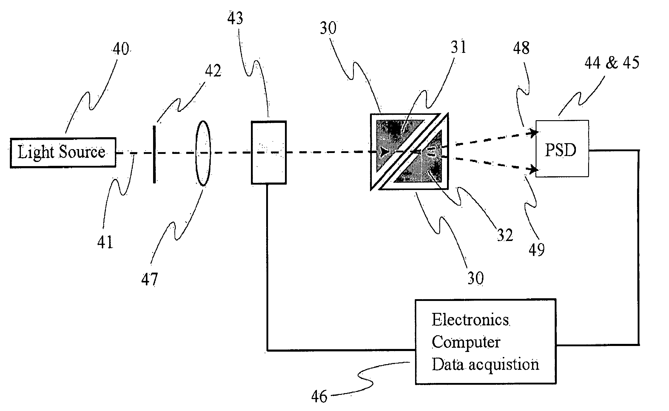
[0059]An apparatus in accordance with one embodiment of the invention is shown in FIG. 4a and consists of a light source 40 such as a laser that emits light which is collimated such that it forms a beam 41. In other embodiments a lamp or in yet another embodiment a light emitting diode may be used together with suitable optics such a lens or a lens-system 47. These light sources may be used at different parts of the electromagnetic spectrum and may be coupled with a monochromater to select a particular wavelength. Said light is then in one embodiment linearly polarized by a polarizer 42 or some suitable combination of polarization optics before it is incident onto a polarization modulator 43 such as a photoelastic modulator (PEM), such as a HINDS Type II FS47. If the light is incident with the correct angle of polarization with respect to the axes of the PEM, the state of the light polarization will modulate, including from left- to right-circularly polarized. In another embodiment ...


PUM


Abstract

A system and method for detection and measurement of circular birefringences in materials that exhibit the Faraday effect. The method and apparatus permit detection of optical activities via the difference in the directions of propagation the left- and the right-circularly polarized light (components). A beam of light is directed at an interface formed by the optically active medium and another medium such that a difference in the angles of refraction and / or reflection and / or diffraction between the left- and the right-circularly polarized components of the light beam can be detected. The difference in the propagation directions between the two circularly polarized light components is measured on a position sensitive detector and / or is detected as an intensity difference.

Description

CROSS-REFERENCE TO RELATED APPLICATIONS[0001]The present application claims the benefit of the filing date of U.S. Provisional Patent Application Ser. No. 60 / 806,074 entitled “Circular Birefringence Refractometer: Method And Apparatus For Measuring Optical Activity” and filed on Jun. 28, 2006 by inventors Peer Fischer and Ambarish Gosh.STATEMENT REGARDING FEDERALLY FUNDED RESEARCH[0002]None.BACKGROUND OF THE INVENTION[0003]1. Field of the Invention[0004]The present invention relates to systems and methods for detection and measurement of circular birefringences in materials, such as optically active (chiral) liquids and materials that exhibit the Faraday effect.[0005]2. Brief Description of the Related Art[0006]An isotropic optically active medium, such as a chiral liquid, is characterized by a difference in the refractive indices for left- and right-circularly polarized light. This refractive index difference is known as circular birefringence and gives rise to the rotation of the ...

Claims


Application Information

Patent Timeline
Patent Type & Authority Patents(United States)
IPC IPC(8): G01J4/00
CPCG01N21/23G01J4/02
Inventor FISCHER, PEERGHOSH, AMBARISH
Owner PRESIDENT & FELLOWS OF HARVARD COLLEGE
Learn More