
Vectorized software packet forwarding

a software packet and vector technology, applied in the field of network communication, can solve the problems of reducing affecting the speed of forwarding engine, and affecting the speed of forwarding graph, so as to reduce the number of data reads performed in the forwarding graph, increase the vector size, and prevent processing delays

Active Publication Date: 2011-06-14
CISCO TECH INC
View PDF6 Cites 34 Cited by
  • Summary
  • Abstract
  • Description
  • Claims
  • Application Information

AI Technical Summary

Benefits of technology

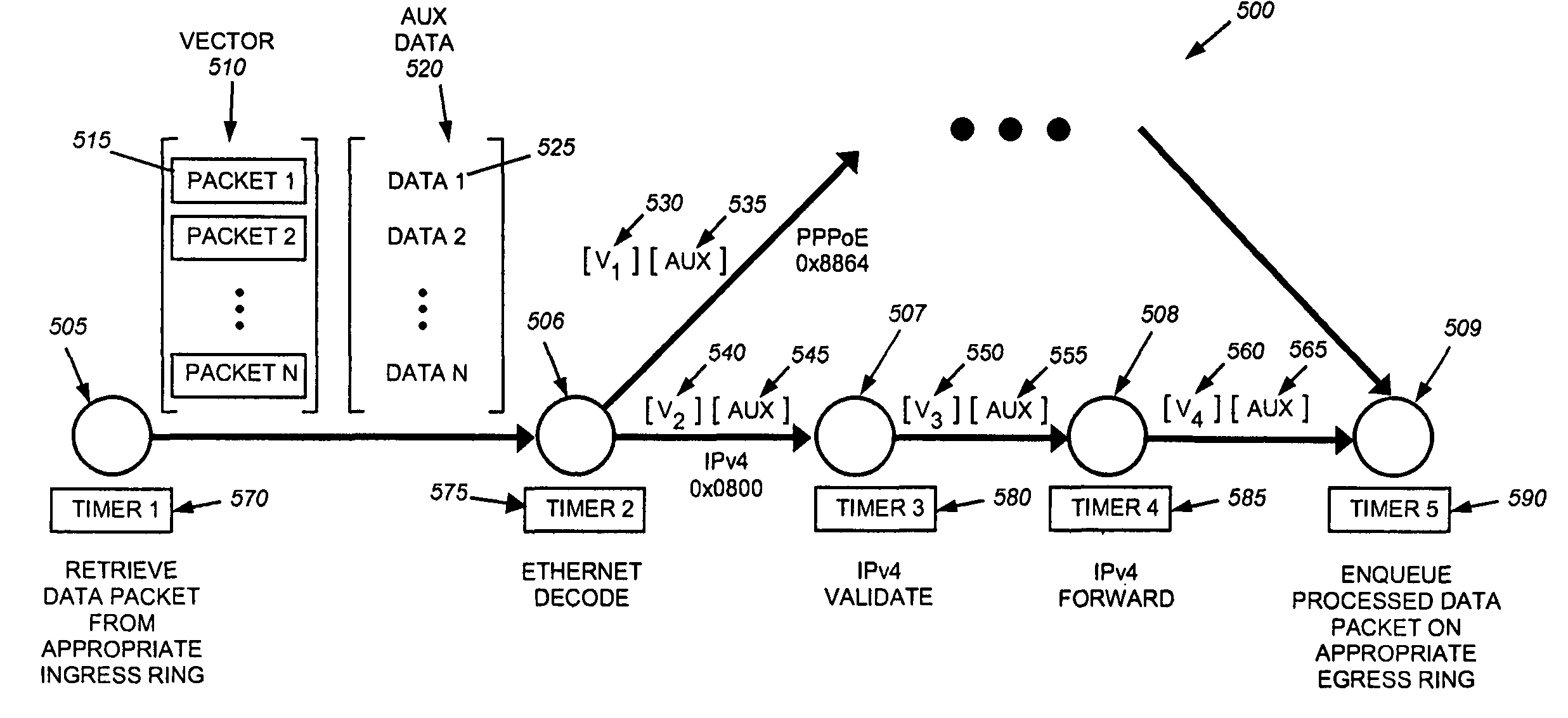
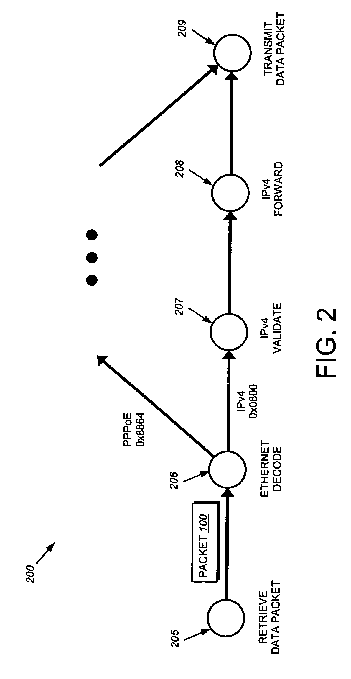
[0020]The present invention provides an intermediate network node that is configured to forward a plurality of packets concurrently, e.g., as a vector, rather than one packet at a time. As such, the node can load a single sequence of forwarding instructions that may be repeatedly executed for packets in the vector. Thus, the instructions are loaded into instruction cache (I-cache) memory once per vector and not once per packet as conventionally done. As a result, the number of I-cache misses per packet is significantly reduced, e.g., by one or more orders of magnitude. Furthermore, vectorizing the intermediate network node's forwarding graph also may reduce the number of data cache (D-cache) misses per packet. For instance, data stored in the D-cache may be used to process a plurality of packets in a vector without having to re-retrieve the data multiple times. By forwarding packets in units of vectors, the intermediate network node reduces the number of I-cache and D-cache misses that occurs per packet, thereby enabling it to forward packets more efficiently (e.g., 2-4 times faster) than in previous implementations.
[0023]By way of example, suppose the intermediate network node's statistics indicate that packets enter the forwarding graph at a relatively low rate, such as at hundreds of packets per second. In this case, the intermediate network node may choose a relatively small vector size to ensure that the time required to accumulate the vector's packets and process the vector through the forwarding graph is less than the target latency. Conversely, the intermediate network node may increase the vector size when packets are input to the graph at a higher rate, such as at millions of packets per second. The intermediate network node preferably recalculates the vector size periodically, e.g., every millisecond, based on its measured statistics. In addition, the intermediate network node may select node-timer intervals for its graph nodes, e.g., depending on measured rates of traffic processed at the graph nodes. For instance, graph nodes that receive packets at relatively faster rates may be associated with shorter node-timer intervals in order to prevent processing delays that could increase the average latency through the forwarding graph above the target latency.
[0024]Still further to the illustrative embodiment, one or more graph nodes may associate a relatively small amount of auxiliary (AUX) data with each packet vector processed at that node. The AUX data may include, inter alia, various packet-related information, such as packet-type identifiers, hash keys, etc. By passing the AUX data between graph nodes, the number of data reads performed in the forwarding graph can be reduced, thereby further decreasing the occurrence of D-cache misses. Advantageously, the intermediate network node may employ one or more vector processors and / or super-scalar processors adapted to process the packet vectors and / or the AUX data in a more efficient manner. In these embodiments, the AUX data may be arranged as a vector that is separate from its associated packet vector. Alternatively, the AUX data may be directly concatenated with its packet vector.

Problems solved by technology

For instance, the forwarding engine may experience a relatively large number of cache misses for each packet processed through the forwarding graph.
As a result, the replaced instruction(s) may not be accessible in the I-cache when the forwarding engine is ready to execute them.
As understood in the art, a cache miss results when the forwarding engine attempts to retrieve information which is not resident in the cache.
Forwarding instructions that are not accessible in the I-cache, and thus result in I-cache misses, are usually retrieved from a predetermined location in a “main” instruction memory coupled to the forwarding engine's processing core.
Thus, the relatively large number of I-cache misses per packet conventionally experienced by the forwarding engine may result in an excessive number of main-memory accesses and / or storage medium accesses which significantly slow the engine's forwarding operations.
In addition, the forwarding engine's performance also may be negatively affected by cache misses that occur in its data cache (D-cache) memory.
Accordingly, cache misses may occur when retrieved data is written to the D-cache memory and consequently overwrites previously-retrieved data.
The processing core may have to consume processing time and resources to later retrieve the over-written, “missed” data from the main memory.
In other words, packets are typically processed by predictable sequences of forwarding instructions which, in turn, result in a predictable pattern of I-cache and D-cache misses.
While the prior code-optimization techniques are effective in reducing the number of I-cache and D-cache misses per packet, they generally do not reduce the number of cache misses enough to have a significant effect on the forwarding engine's performance.

Method used


Image

  • Vectorized software packet forwarding
  • Vectorized software packet forwarding
  • Vectorized software packet forwarding

Examples


Embodiment Construction

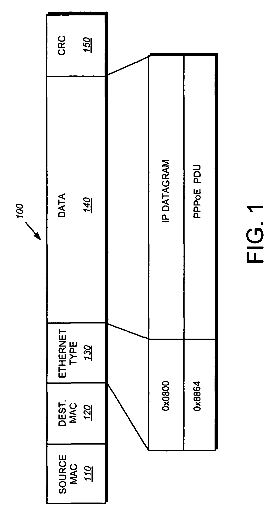
[0034]FIG. 3 is a block diagram of a computer network 300 comprising a collection of interconnected subnetworks and nodes. The network nodes may comprise computers including end nodes 330 and 340, such as a sending end node 320 and a receiving end node 350, and an intermediate network node 400, the latter of which may be a switch or router. The subnetworks 305, 310 included within network 300 are preferably local area networks (LANs) interconnected by the intermediate node 400, although the networks may comprise other communication links, such as wide area networks. Communication among the nodes coupled to the LANs is typically effected by exchanging discrete data packets 100 among the nodes.

[0035]For example, the sending node 320 generates a data packet 100 by encapsulating “payload” data within headers, such as conventional data link and internetwork headers, as the data passes through different layers of a protocol stack. The packet is then transmitted over the network to the int...


PUM


Abstract

An intermediate network node is configured to forward a plurality of packets concurrently, e.g., as a vector, rather than one packet at a time. As such, the node can load a single sequence of forwarding instructions that may be repeatedly executed for packets in the vector. In addition, the intermediate network node adaptively controls the rate at which it processes data packets through a directed forwarding graph. To that end, the intermediate node is configured to dynamically select the number of packets per vector, i.e., vector size, processed at each node of the forwarding graph. Further, the intermediate node also may be configured to dynamically select timing intervals for one or more “node timers” used to control the rate at which packets traverse through the graph. Illustratively, the vector size and node-timer intervals are selected so that the average latency through the forwarding graph is less than a predetermined target latency, e.g., 50 microseconds (μs).

Description

FIELD OF THE INVENTION[0001]This invention relates generally to network communications, and, more specifically, to an efficient technique for forwarding data packets in an intermediate network node, such as a router or switch.BACKGROUND OF THE INVENTION[0002]A computer network is a geographically distributed collection of interconnected subnetworks for transporting data between nodes, such as computers. A local area network (LAN) is an example of such a subnetwork. The network's topology is defined by an arrangement of client nodes that communicate with one another, typically through one or more intermediate network nodes, such as a router or switch. As used herein, a client node is an endstation node that is configured to originate or terminate communications over the network. In contrast, an intermediate network node is a node that facilitates routing data between client nodes. Communications between nodes are typically effected by exchanging discrete packets of data according to ...

Claims


Application Information

Patent Timeline
IPC IPC(8): H04L12/28
CPCH04L12/4625H04L49/3009H04L45/028H04L45/00
Inventor BARACH, DAVID RICHARDDRESSELHAUS, ELIOT
Owner CISCO TECH INC
Learn More