Apparatus and method for monitoring speaker cone displacement in an audio speaker

a technology for audio speakers and antennas, applied in the field of antennas and methods for monitoring speaker cone displacement in audio speakers, can solve the problems of cone motion and the size and mass of sensors, significant distortion, and the cost of implanting sensors in the diaphragm of the speaker

Active Publication Date: 2011-06-14
TEXAS INSTR INC
View PDF15 Cites 147 Cited by
  • Summary
  • Abstract
  • Description
  • Claims
  • Application Information

AI Technical Summary

Benefits of technology

[0012]It is, therefore, an object of the present invention to provide an inexpensive and compact apparatus and method for monitoring or measuring speaker cone displacement in audio speakers that does not significantly affect operation of a speaker.

Problems solved by technology

For example, in a subwoofer, cone excursions can be quite large, especially at low frequencies, leading to suspension non-linearities that result in significant distortion.
Important impediments to widespread adoption of such technologies have been the costs associated with implanting sensors in the diaphragm of the speaker to measure or monitor cone motion and the size and mass of the sensors.
The costs reduced profit margins sufficiently to make the improvements unattractive.
The size has been a design challenge for small, compact speaker units of the sort often sought in today's market.
If the mass of a sensor is too great it will interfere with or skew the performance of a speaker.
However, such an arrangement requires providing electrical leads to the accelerometer.
Hall's apparatus adds mass and bulk that can skew indications of cone motion, risk wire breakage from metal fatigue associated with motion of the cone and limit how compactly the speaker may be made.
Other aspects of Hall's apparatus, such as a requirement for a dust cap, add further to the cost and bulk to a speaker.
Such apparatuses add complexity, cost and bulk to a speaker.
It is a complex arrangement fraught with opportunities for breakdown and adds cost, bulk and mass to a speaker.
A significant problem with using optical sensor systems in addition to adding complexity, cost, mass and bulk is that they are subject to being rendered less efficient, unreliable or even inoperative by dust or other debris buildup.

Method used


Image

  • Apparatus and method for monitoring speaker cone displacement in an audio speaker
  • Apparatus and method for monitoring speaker cone displacement in an audio speaker
  • Apparatus and method for monitoring speaker cone displacement in an audio speaker

Examples


first embodiment

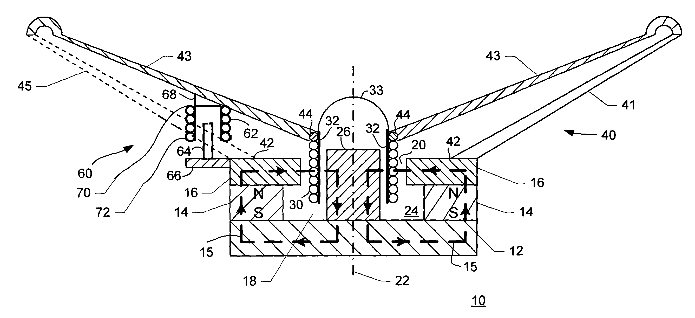
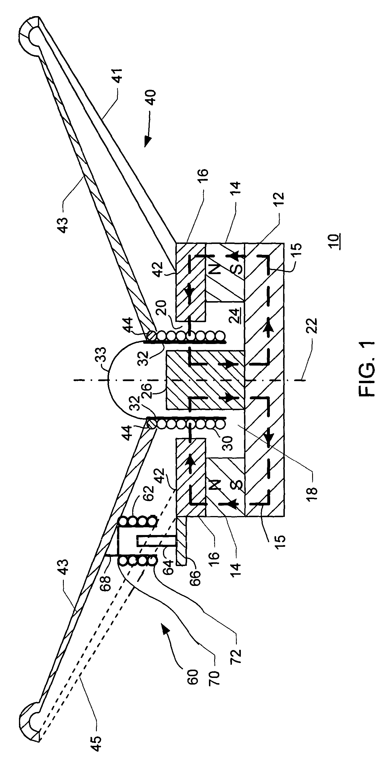
[0021]FIG. 1 is a schematic partial section diagram of a speaker using the apparatus of the present invention. In FIG. 1, a speaker 10 includes a bottom plate 12, a permanent magnet 14 affixed to bottom plate 12 and a top plate 16 affixed to permanent magnet 14. Permanent magnet 14 has an aperture 18 substantially oriented about an axis 22. Permanent magnet 14 has a north pole N and a south pole S. Top plate 16 has an aperture 20 oriented about axis 22. Apertures 18, 20 cooperate with bottom plate 12 to establish a cavity 24 within which is affixed a ferrous pole piece 26. A voice coil 30 is situated in part within cavity 24 oriented about pole piece 26 wound upon a voice coil bobbin 32. An air gap is established between voice coil 30 and top plate 16 when speaker 10 is in an assembled orientation with pole piece 26, bobbin 32 and voice coil 30 installed in cavity 24. A dust cap 33 may be integrally formed with or attached to bobbin 32. In the assembled orientation, magnetic flux (i...

second embodiment

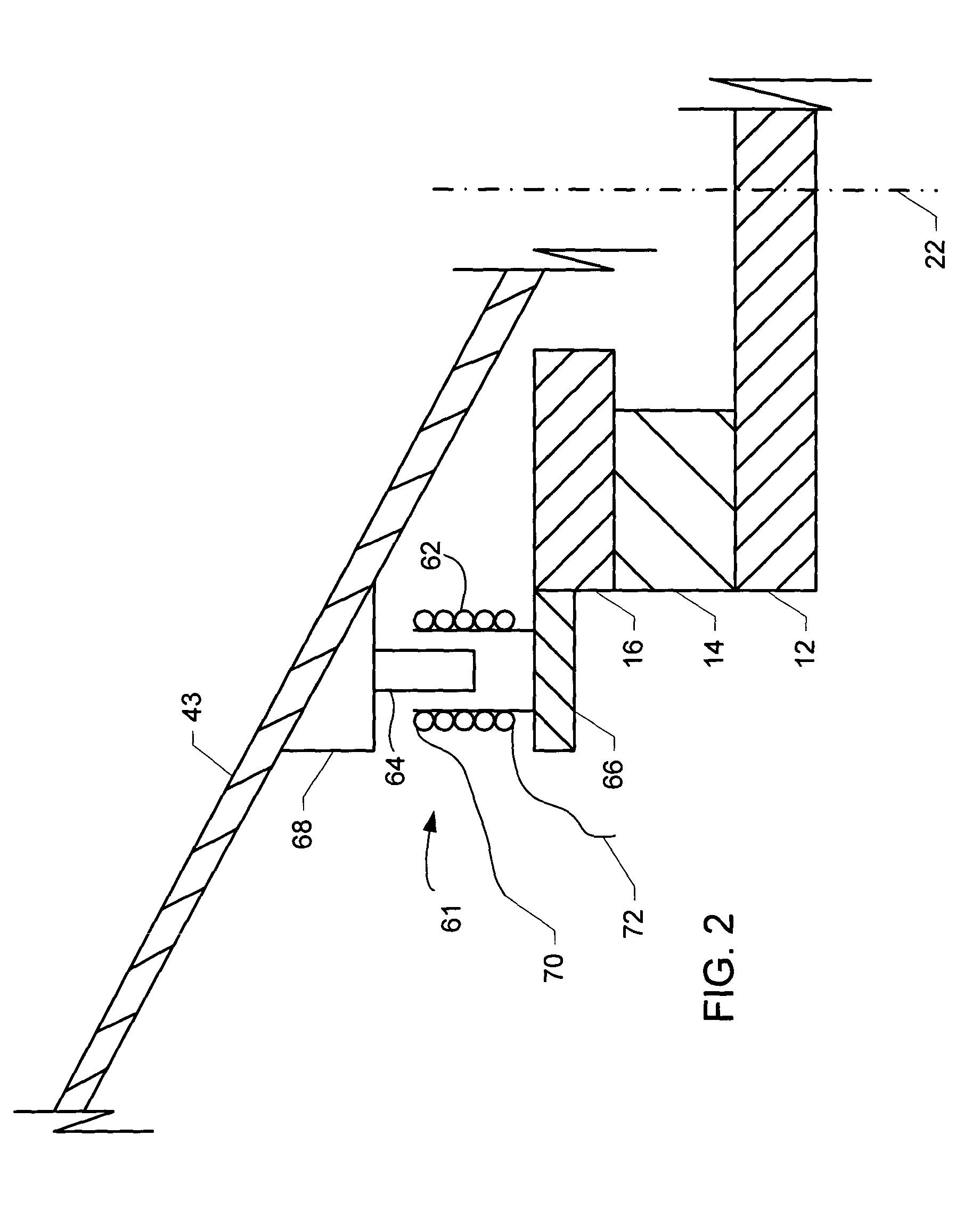
[0028]FIG. 2 is a schematic diagram of a portion of a speaker using the apparatus of the present invention. In FIG. 2, sensor apparatus 61 includes an electromagnetic coil structure 62 and a ferrous core structure 64. Electromagnetic coil structure 62 is affixed to a supplemental top plate 66. Supplemental top plate 66 may be configured as an integral portion of top plate 16. Ferrous core structure 64 is affixed to cone 43 at the rear of cone 43. Ferrous core structure 64 is preferably affixed with cone 43 using wedge 68. Wedge 68 is preferably configured appropriately to cause ferrous core structure 64 to respond to motion by cone 43 in directions substantially parallel with axis 22. Wedge 68 may be eliminated or altered in mounting ferrous core structure 64. The angle between direction of motion of ferrous core structure 64 in response to motion by cone 43 and axis 22 may be mathematically accounted for in signal treatment circuitry (not shown in FIG. 2).

[0029]An input signal may ...


PUM


Abstract

An apparatus for monitoring speaker cone displacement in an audio speaker includes: (a) an electromagnetic coil structure; (b) a ferrous core structure; the ferrous core structure and the electromagnetic coil structure being mounted with the speaker to effect variable electromagnetic coupling between the ferrous core structure and the electromagnetic coil structure as the speaker cone moves; (c) a signal injecting circuit coupled with the electromagnetic coil structure for injecting a predetermined input signal into the electromagnetic coil structure; and (d) a signal monitoring circuit coupled with the electromagnetic coil structure; the signal monitoring circuit receiving an output signal from the electromagnetic coil structure and generating an indicating signal based upon the output signal; at least one signal characteristic of the indicating signal being related with the cone displacement.

Description

BACKGROUND OF THE INVENTION[0001]The present invention is directed to audio speakers, sometimes referred to as loudspeakers, and especially to reducing distortion caused by non-linear characteristics in audio speakers.[0002]In recent years, loudspeaker engineers have begun employing various servo-related technologies in the design of loudspeakers seeking to reduce distortion and modify the dynamics of the speaker and its enclosure. For example, in a subwoofer, cone excursions can be quite large, especially at low frequencies, leading to suspension non-linearities that result in significant distortion. Motional feedback signals combined with carefully designed compensators can alleviate these distortion problems. In addition, motional feedback signals can be employed to modify the suspension properties allowing designers to modify the speaker's response without having to physically modify the enclosure or the speaker design. Important impediments to widespread adoption of such techno...

Claims


Application Information

Patent Timeline
Patent Type & Authority Patents(United States)
IPC IPC(8): H04R29/00H03G5/00H04R3/00H04R9/06
CPCH04R9/063H04R29/003
Inventor FEDIGAN, STEPHEN JOHN
Owner TEXAS INSTR INC
Why Eureka
Try Eureka