Corrugated tubular energy absorbing structure

a technology of energy absorption structure and corrugated tubular structure, which is applied in the direction of shock absorption device, roof, elastic damper, etc., can solve the problems of inability to achieve ideal energy absorption characteristics, inability to provide all of these attributes, and inability to optimally optimize the efficiency of absorbing energy in prior art tubular structure, etc., to achieve low cost, constant force level, and efficient absorption of impact energy during impa

Inactive Publication Date: 2011-06-21
O FLEX GRP
View PDF30 Cites 10 Cited by
  • Summary
  • Abstract
  • Description
  • Claims
  • Application Information

AI Technical Summary

Benefits of technology

[0010]It is an object of the present invention to provide a tubular stroking energy absorbing structure which can efficiently absorb impact energy during impact at nearly constant force levels; can function as a low cost spacer in vehicle exterior applications; can incorporate a low cost push snap attachment device for vehicle interior applications; provide high vibration and noise damping, and provide consistent impact performance over a wide range of temperatures and environmental conditions.
[0012]In one embodiment, the energy absorbing structure is a tube made of a molded or extruded polymer, such as high density polyethylene (HDPE). The tube has a substantially quadrangular cross-section with four corrugated walls and rounded corners. The corrugations on each of the side walls are aligned transverse to the length of the tube. Optionally, the interior of the tube can be filled (or partially filled) with foam of different densities to vary the impact performance of the structure.
[0019]The novel energy absorbing structure of the present invention has application to vehicle interiors, exteriors, and bumpers by providing very efficient (square wave force vs. deflection) energy absorption during impact at a nearly constant force level. These structures are capable of providing a “soft” peak pedestrian knee acceleration of less than 150 G when impacted at 40 KMH with the European Union (EU) lower leg form test fixture. The structures also incorporate a high level of vibration / noise damping. In motor vehicle applications, an energy absorbing structure of the present invention can function as a low cost spacer between vehicle fascia covers and vehicle body structure and as a low cost snap fit attachment device for interior trim applications. The invention has specific application to vehicle bumper systems which must meet the FMVSS 2.5 and 5 mph impact test standards, the EU pedestrian lower leg form 40 KMH test requirements, and the FMVSS 201 u head impact test standards. The corrugated walls progressively deform (stroke) during impact thereby providing a near perfect square wave force vs. deflection energy absorption curve at any predetermined force level, which is a function of the corrugated wall geometry, wall thickness, and wall material.

Problems solved by technology

Unfortunately, prior art tubular structures have not been optimally efficient in absorbing energy produced by external impacts to the vehicle.
Unfortunately, prior art tubular structures have not provided a methodology for achieving ideal energy absorbing characteristics.
Prior art energy absorbing structures cannot provide all of these attributes in combination.

Method used


Image

  • Corrugated tubular energy absorbing structure
  • Corrugated tubular energy absorbing structure
  • Corrugated tubular energy absorbing structure

Examples


Embodiment Construction

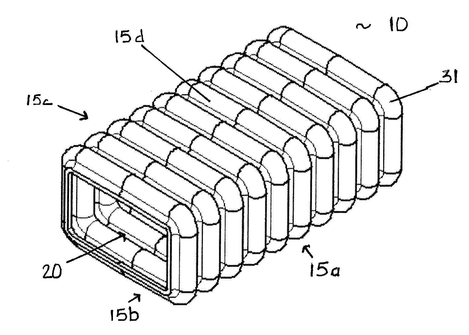
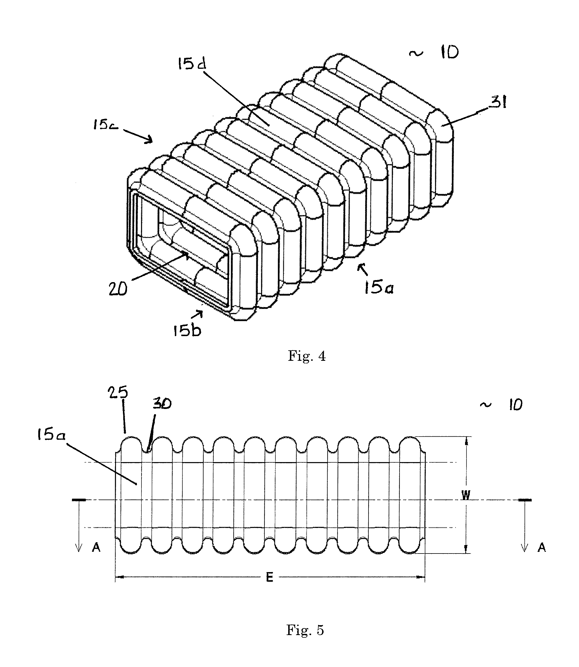
[0048]A preferred embodiment of the energy absorbing structure of the present invention is shown FIGS. 4-8. The basic structure is a closed section polygonal, circular, or substantially quadrangular tube. In the embodiment of FIGS. 4-8, the tube 10 has a substantially quadrangular cross-section defined by four side walls 15a-d and a hollow interior 20. As shown on FIGS. 5 and 6, for design and modeling purposes, the tube 10 has a length E that is determined by the space available in the particular energy absorbing application. The rectangular cross-section of the tube is defined by a longer outer dimension L and a shorter outer dimension W. The aspect ratio of the tube 10 can therefore be represented by L / W.

[0049]In this embodiment, each of the side walls 15a-d is corrugated with rounded corners 31. As best seen in FIGS. 5, 7, and 8, the side walls 15a-d have a preferred corrugation geometry in which the corrugations have a continuous constant radius R with no intervening flat spots...


PUM


Abstract

An energy absorbing tubular structure is formed of a molded or extruded polymer. The tube has a quadrangular cross-section with rounded corners. The walls of tube are corrugated with alternating convex and concave corrugations surfaces having a continuous constant radius, preferably with no flat spots. The corrugated walls have a constant thickness. The corrugations progressively deform during impact thereby providing a near perfect square wave force vs. deflection energy absorption curve at any predetermined nearly constant force level. The tube may be filled with polymer foam to vary the impact performance of the structure.

Description

CROSS-REFERENCES TO RELATED APPLICATIONS[0001]This application is a non-provisional application which claims benefit of U.S. Patent Application Ser. No. 60 / 836,681 filed Aug. 10, 2006, entitled “AUTOMOTIVE TUBULAR ENERGY ABSORBER” which is hereby incorporated by reference.STATEMENT REGARDING FEDERALLY SPONSORED RESEARCH OR DEVELOPMENT[0002]Not ApplicableREFERENCE TO SEQUENCE LISTING OR COMPUTER PROGRAM LISTING APPENDIX[0003]Not ApplicableBACKGROUND OF THE INVENTION[0004]The present invention generally relates to structures used to absorb energy from impact forces applied to the exterior and interior components of motor vehicles. More particularly, this invention pertains to tubular energy absorbing structures that can provide a substantially constant reaction force by progressively deforming and absorbing energy during impact.[0005]The Federal Motor Vehicle Safety Standards (FMVSS) impose performance requirements on automobile bumpers to minimize vehicle damage and on interior trim ...

Claims


Application Information

Patent Timeline
Patent Type & Authority Patents(United States)
IPC IPC(8): F16F7/12
CPCB60R13/0225B60R13/025B60R19/18B60R21/04B62D29/043B62D21/15B60R21/0428B60R2019/184B60R2021/0435B60R2021/0442B60R2013/0287B60R19/02F16F7/12B62D25/00
Inventor GLANCE, PAUL C.WINTER, SIDNEY T.BAUER, ROBERT J.FINCH, EDDY R.TOKARZ, BRYANT A.
Owner O FLEX GRP
Why Eureka
Try Eureka