Hybrid towing bumper beam assembly

Active Publication Date: 2019-11-28
SABIC GLOBAL TECH BV
View PDF0 Cites 1 Cited by
  • Summary
  • Abstract
  • Description
  • Claims
  • Application Information

AI Technical Summary

Benefits of technology

[0038]An exemplary filled resin is STAMAX™ resin, which is a long glass fiber filled polypropylene resin also commercially available from SABIC. Some possible reinforcing materials include fibers, such as glass, carbon, and so forth, as well as combinations comprising at least one of the foregoing; e.g., long glass fibers and/or long carbon fiber reinforced resins. For example, carbon fiber reinforced polymeric composites can be utilized to form the energy absorbing assembly. Carbon fiber reinforced polymeric composites can be used as a coating (e.g., skin) on the energy absorbing assembly or portions thereof to provide the desired structural integrity to the energy absorbing assembly. The energy absorbing assembly can be formed from combinations comprising at least one of any of the above-described materials. For example, in some embodiments, the same material can be used to make each component of the energy absorbing assembly (

Problems solved by technology

One of the issues occurring in this situation is the damage the tow assembly might

Method used


Image

  • Hybrid towing bumper beam assembly
  • Hybrid towing bumper beam assembly
  • Hybrid towing bumper beam assembly

Examples


first embodiment

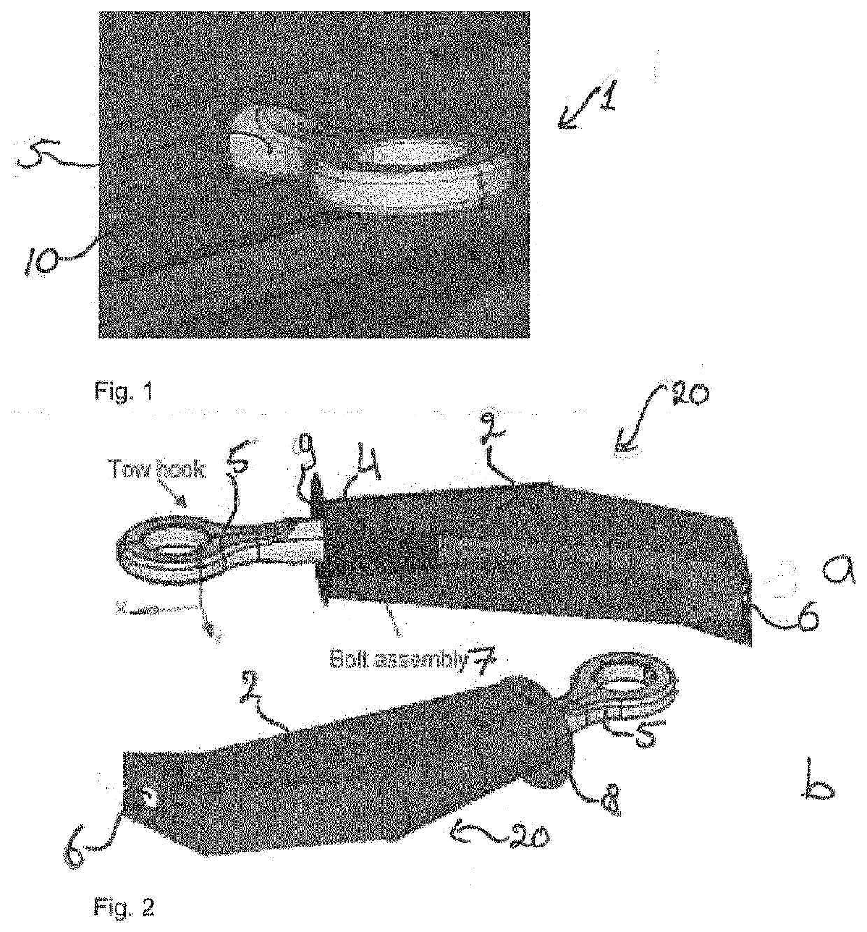
[0061]FIG. 1 shows a hybrid towing bumper rear beam assembly 1 according to the present invention in perspective view. The hybrid towing bumper rear beam assembly 1 comprises a fascia 10 and a towing hook 5. The towing hook 5 is fastened into a metal insert 2, forming a towing assembly 20, see FIGS. 2a and b. The metal insert 2 has a receiving portion 4, a positioning flange 8 and a connection portion 6. The receiving portion 4 is for receiving and fastening the towing hook 5 to the metal insert 2, for instance by means of a bolt assembly 7. The receiving portion is provided with an opening 9 for insertion of the towing hook 5 into the receiving portion. The connection portion 6 is for connection of the metal insert to a vehicle (not shown), such that the towing assembly is connected to a body of the vehicle (not shown) and thereby transferring the towing load to the body of the vehicle. The positioning flange 8 is used to stabilize the position of the metal insert in the bumper bea...

second embodiment

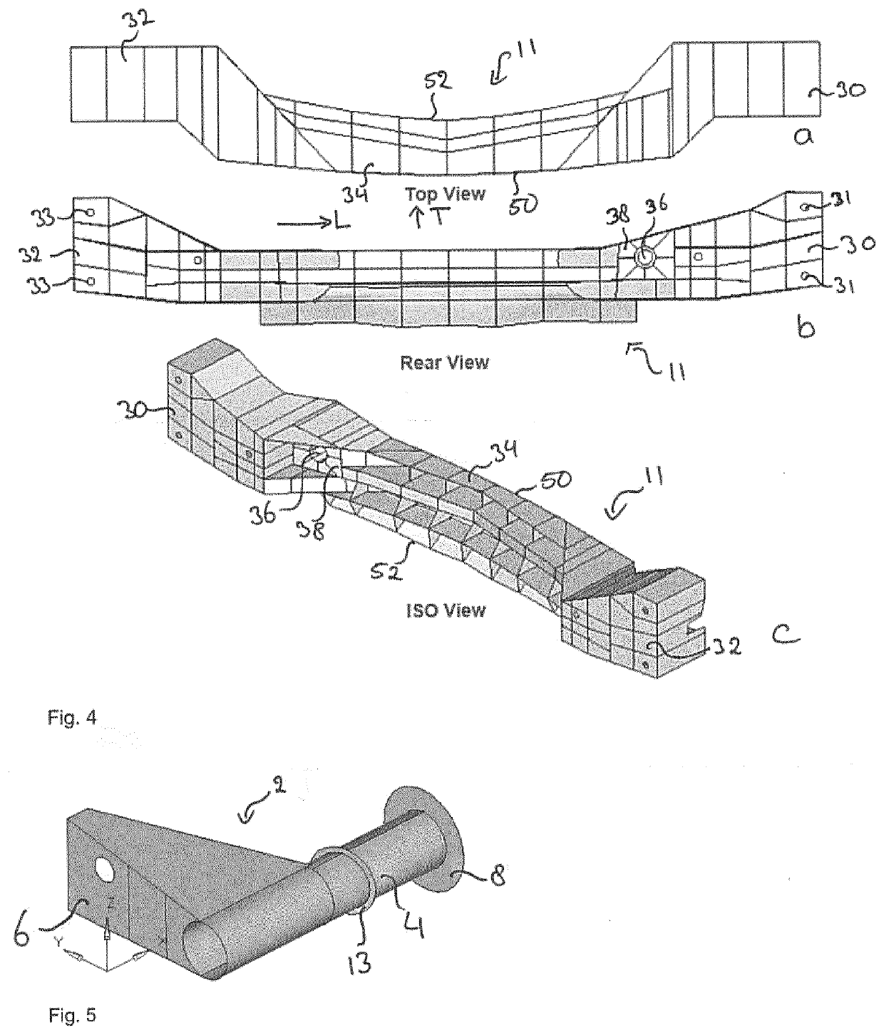
[0063]FIG. 5 shows the metal insert 2 for the hybrid towing bumper rear beam assembly 1 having a first positioning flange 8, a second positioning flange 13, a receiving portion 4 and a connection portion 6.

[0064]FIGS. 6a to c show several views of a second embodiment of the hybrid towing bumper rear beam assembly 1. The metal insert 2 is embedded in the bumper beam 11 at the insertion location 38. The first and second positioning flanges 8, 13 of the metal insert 2 stabilize the position of the metal insert 2 in the bumper beam 11. The metal insert 2 is located near the first end portion 30 of the bumper beam 11, which is off center in the bumper beam 11. FIG. 6b shows a front view of the hybrid towing bumper rear beam assembly 1 of FIG. 6a, showing the front side 50 of the bumper beam 11. The first positioning flange 8 can be seen, as well as the opening 9 to the receiving portion 4 of the metal insert 2. Additionally, the connection portion 6 for connecting the metal insert 2 to a...


PUM


Abstract

Hybrid energy absorbing assembly for attachment to a vehicle for a vehicle, comprising a bumper beam comprising a plastic material; and a towing assembly, wherein the towing assembly comprises a metal insert. The invention also relates to a metal insert for such a hybrid energy absorbing assembly. Moreover, the invention relates to a vehicle provided with such a hybrid towing bumper beam assembly, wherein the metal insert is connected to a body-in-white of the vehicle. Furthermore, the invention relates to a method for manufacturing such a hybrid towing bumper beam assembly for a vehicle, the method comprising placing the metal insert in a mold; introducing molten thermoplastic material, to a mold to in site form the energy absorbing assembly and thus overmolding the metal insert with the thermoplastic material, thereby embedding the metal insert in the bumper beam.

Description

BACKGROUND OF THE INVENTIONField of the Invention[0001]The present invention relates to a hybrid towing bumper beam assembly, comprising a metal insert and a bumper rear beam. The invention also relates to a metal insert for a bumper rear beam. Furthermore, the invention relates to a method of manufacturing such a hybrid towing bumper beam assembly.Description of the Related Art[0002]A bumper beam assembly, in particular a rear bumper beam assembly, is part of every motor vehicle for protection against low speed vehicle collision condition. Such bumper beam assemblies are designed in such a way that they absorb a large portion of the energy during collision. The rear bumper assembly typically includes a beam that extends transversely across the rear end of the motor vehicle.[0003]Metals have been in used for both bumpers and tow assemblies, because of their high rigidity. However, due to recent regulations and to increased fuel efficiency, recent focus has been on reducing the weigh...

Claims


Application Information

Patent Timeline
IPC IPC(8): B60D1/56B60R19/18
CPCB60D1/243B60D1/565B60R19/18B60D1/485B60R2019/184B60D1/488B60R19/03B60R2019/1806B60R2019/1833
Inventor KHANDELWAL, RATNESHMUNJURULIMANA, DINESH
Owner SABIC GLOBAL TECH BV
Why Eureka
Try Eureka