Protective circuit and method for multi-level converter

a protection circuit and converter technology, applied in the direction of machines/engines, mechanical equipment, harmonic reduction ac networks, etc., can solve the problems of distorted output voltage waveform, unbalanced neutral point topology of point clamped converters, and wind turbine design

Active Publication Date: 2009-08-11
GENERAL ELECTRIC CO
View PDF3 Cites 93 Cited by
  • Summary
  • Abstract
  • Description
  • Claims
  • Application Information

AI Technical Summary

Problems solved by technology

One challenge for a three-level neutral point clamped converter topology is neutral point unbalance.
During large grid disturbances, however, even when using PWM, the neutral point voltage may diverge away from the zero voltage potential.
The neutral point voltage unbalance will increase voltage stress on the DC link capacitors and converter switches and result in a distorted output voltage waveform.
However, wind turbines must be designed to ride-through large grid disturbances.

Method used


Image

  • Protective circuit and method for multi-level converter
  • Protective circuit and method for multi-level converter
  • Protective circuit and method for multi-level converter

Examples


Embodiment Construction

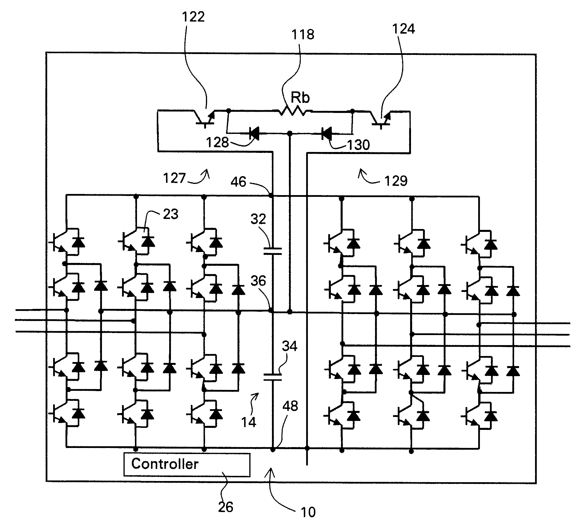
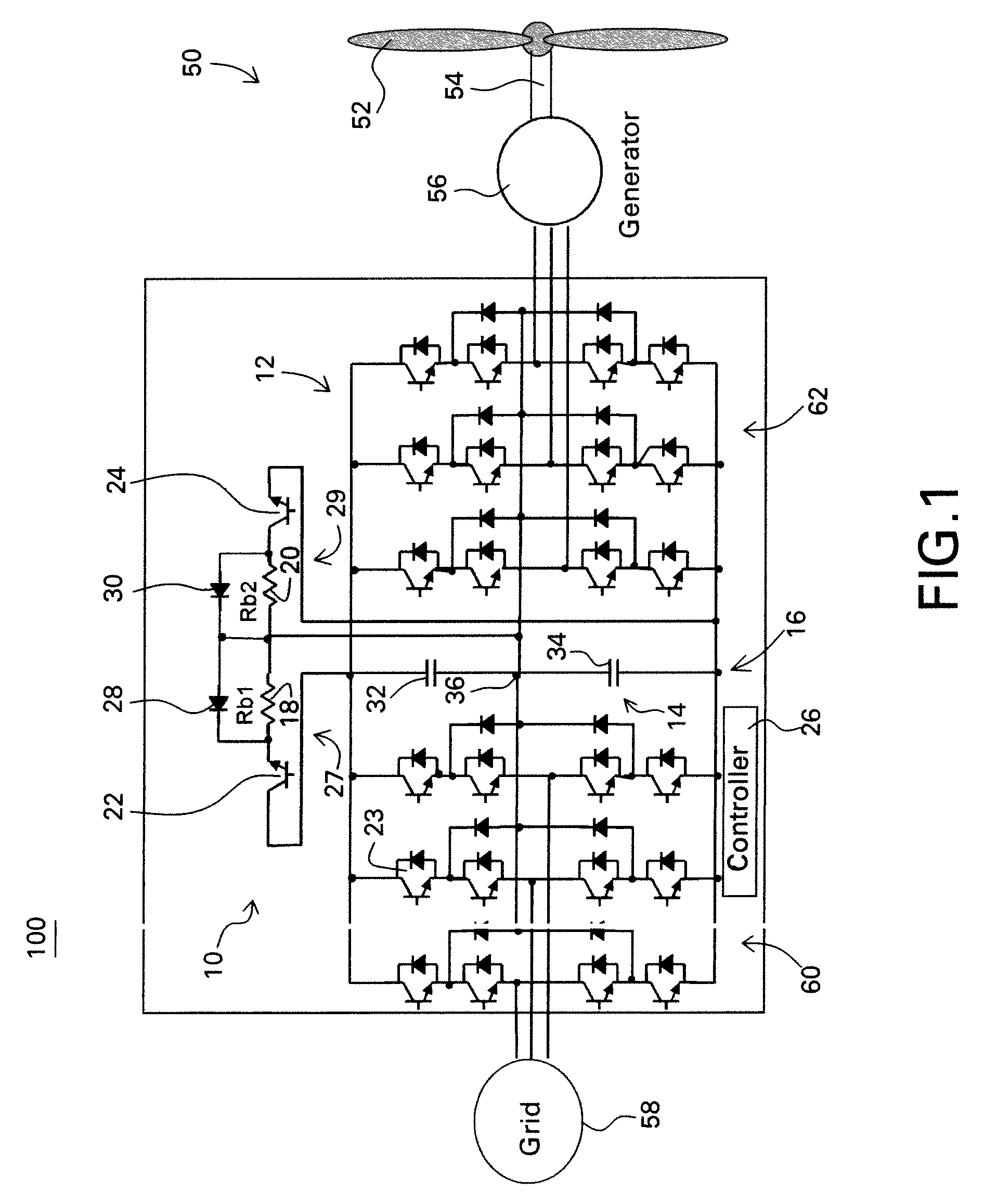
[0019]FIG. 1 illustrates a wind turbine 50 embodiment for purposes of example. In a wind turbine, blades 52 are coupled to a shaft 54 which drives a generator 56, either directly or through a gearbox. The voltage resulting from generator 56 has a variable frequency that is converted to a fixed frequency by a converter system 12 before being supplied to a grid 58. For simplicity of illustration, conventional transformer and filter elements between the converter system and the grid are not shown in FIG. 1. Although a wind turbine generator is shown for purposes of example, any type of generator may be included with these embodiments being particularly useful for renewable energy source generators. Additionally, although a generator is shown in FIG. 1, as is further described with respect to FIG. 9, the embodiments disclosed herein are applicable to other types of loads such as motors in motor drives and a load bank in an uninterruptible power supply (UPS), for example.

[0020]As discuss...


PUM


Abstract

A protective circuit for a multi-level converter including a DC link capacitor bank includes: an energy absorbing element; switches, wherein at least two of the switches each couple the energy absorbing element to the capacitor bank; and a controller configured to provide control signals to the switches to selectively actuate the switches to enable control of energy dissipation and to enable control of voltage balance on the capacitor bank of the multi-level converter.

Description

BACKGROUND[0001]The described embodiments relate generally to power converters.[0002]Typically two-level power converters are used to convert wind turbine generated power into grid power. Two-level converters are cost effective at lower power levels. As power levels increase, a multi-level (herein meaning three or more) power converter embodiment is thought to be more cost effective.[0003]One challenge for a three-level neutral point clamped converter topology is neutral point unbalance. For optimal operation of a typical three-level converter, the neutral point of the capacitor bank must be maintained at a voltage near the mid-point of the DC link. During normal operation, a three level converter pulse width modulation (PWM) strategy can be used to balance (center) the neutral point.[0004]For PWM balance control, the basic principle is to inject an additional compensating signal during PWM modulation. By this technique, the neutral point current is regulated to charge or discharge ...

Claims


Application Information

Patent Timeline
Patent Type & Authority Patents(United States)
IPC IPC(8): H02H7/122H02M5/458
CPCH02M1/32H02M7/487H02M5/4585F03D15/00F03D9/255H02H7/12H02J3/01H02M1/0048Y02B70/10Y02E10/72Y02E10/76Y02E40/40
Inventor TEICHMANN, RALPHWANG, CHANGYONGDELMERICO, ROBERT WILLIAMTAN, ZHUOHUIROESNER, ROBERTDAI, RENCHANG
Owner GENERAL ELECTRIC CO
Why Eureka
Try Eureka