Vehicular propeller shaft

a propeller shaft and shaft technology, applied in the field of propeller shafts, can solve the problems of low degree of workability and difficulty in formation, and achieve the effects of reducing thickness and weight, improving fuel economy of the vehicle, and reducing weigh

Active Publication Date: 2018-08-16
TOYOTA JIDOSHA KK
View PDF2 Cites 1 Cited by
  • Summary
  • Abstract
  • Description
  • Claims
  • Application Information

AI Technical Summary

Benefits of technology

[0015]According to the second mode of the invention, the second tubular member has a smaller wall thickness than the first tubular member, so that the propeller shaft can be reduced in weight, whereby fuel economy of the vehicle can be improved.
[0016]According to the third mode of the invention, the second tubular member has a larger dimension in its axial direction than the first tubular member, so that the propeller shaft can be effectively reduced in thickness and weight, whereby the fuel economy of the vehicle can be further improved.
[0017]According to the fourth mode of the invention wherein the difference between the strength values of the materials of the first and second tubular members is at least 100 MPa, the first tubular member can be suitably formed so as to effectively absorb the impact energy generated upon collision of the vehicle, while the second tubular member having the comparatively small wall thickness can improve the fuel economy of the vehicle.
[0018]According to the fifth mode of the invention wherein the second tubular member has the same outside diameter as the small-diameter cylindrical section of the first tubular member and is joined to the small-diameter cylindrical section. Accordingly, the second tubular member is joined over its entire wall in cross section to the small-diameter cylindrical section of the first tubular member, so that an impact load is uniformly applied to the second tubular member over its entire wall upon transmission of the impact energy from the first tubular member to the second tubular member in the event of collision of the vehicle, whereby the second tubular member can stably receive the impact load over its entire wall at its axial end joined to the first tubular member. Further, the strength of the second tubular member having the same outside diameter as the small-diameter cylindrical section of the first tubular member can be maximized. In addition, the thus increased strength of the second tubular member permits its accordingly reduced wall thickness, and a consequent improvement of the fuel economy of the vehicle.
[0019]According to the sixth mode of the invention, the first tubular member has the another small-diameter cylindrical section having the smaller outside diameter than the large-diameter cylindrical portion and the above-described small-diameter cylindrical section, and the another tapered cylindrical section formed between the other end of the large-diameter cylindrical section and the above-described another small-diameter cylindrical section, so that the first tubular member may be initially deformed at an appropriate one of its various sections including the tapered cylindrical sections. Further, the first tubular member can be deformed in a larger number of various fashions, so that the first tubular member can absorb a larger amount of impact energy upon collision of the vehicle.
[0020]According to the seventh mode of the invention, the above-described another small-diameter cylindrical section is connected to the first universal joint through the shaft the axial length of which is variable, and the second tubular member is connected, at its axial end remote from the first tubular member, to the second universal joint. Accordingly, vibrations of the propeller shaft in its axial direction due to vertical movements of the drive wheels can be easily absorbed, so that the rotary motion of the drive power source can be stably transmitted to the drive wheels through the propeller shaft, irrespective of the vertical movement of the drive wheels.

Problems solved by technology

Where the material having a high degree of tensile strength, for example, a high tensile-strength steel tube is used for the propeller shaft, however, this material has a low degree of workability, and difficulty to form the propeller shaft having a complicated geometrical configuration for effective absorption of the impact energy in the event of collision of the vehicle.

Method used


Image

  • Vehicular propeller shaft
  • Vehicular propeller shaft
  • Vehicular propeller shaft

Examples


first embodiment

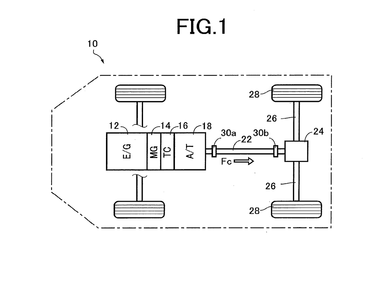
[0027]FIG. 1 is the schematic view showing a drive system of a hybrid vehicle 10 to which the present invention is applicable. As shown in FIG. 1, the vehicle 10 is of an FR type (front-engine rear-drive type), and is provided with an engine 12 as a vehicle drive power source in the form of an internal combustion engine such as a gasoline engine or a diesel engine, and a motor / generator 14 functioning as an electric motor and an electric generator. Outputs or rotary motions of the engine 12 and motor / generator are transmitted to an automatic transmission 18 through a fluid-operated power transmitting device in the form of a torque converter 16, then to a differential gear device 24 through a propeller shaft 22, and finally to left and right rear drive wheels 28 through respective axles 26.

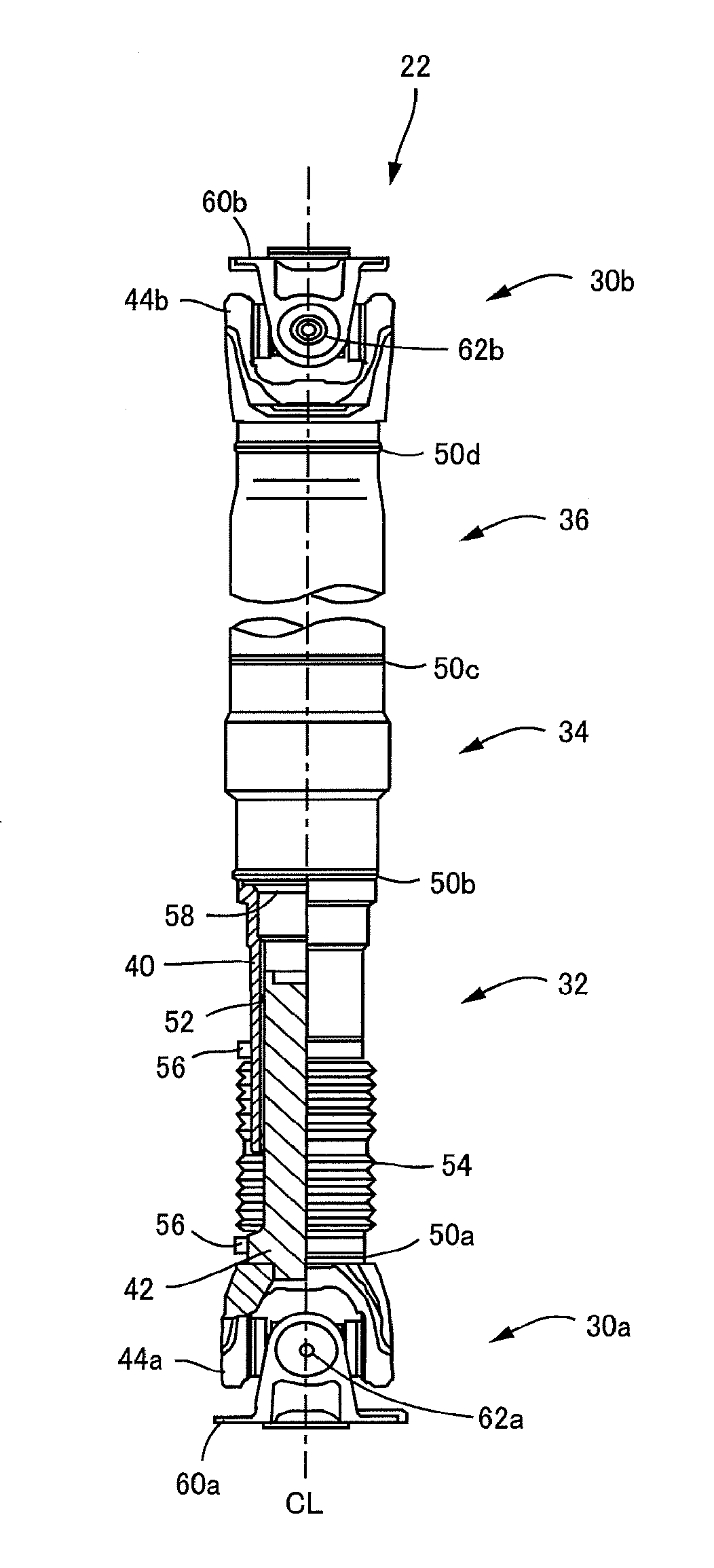
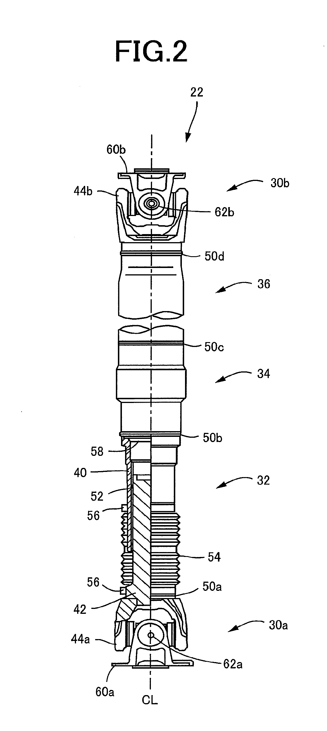
[0028]FIG. 2 is the view showing the vehicular propeller shaft 22 according to the present invention. The propeller shaft 22 is constituted by a front portion 32, an intermediate portion 34 and a r...

second embodiment

[0046]FIG. 4 is the cross sectional view illustrating the intermediate portion 34 of the propeller shaft 22 according to a second embodiment of the invention. The intermediate portion 34 consists of: the large-diameter cylindrical section 46a having the outside diameter d3; the first small-diameter cylindrical section 46b having the outside diameter d4; and the first tapered cylindrical section 48a formed between the large-diameter cylindrical section 46a and the first small-diameter cylindrical section 46b. The first tapered cylindrical section 48a has the first taper angle θ1 with respect to the first small-diameter cylindrical section 46b. The first small-diameter cylindrical section 46b of the intermediate portion 34 is integrally welded to the rear portion 36 having the outside diameter d5 equal to the outside diameter d4 of the first small-diameter cylindrical section 46b. The rear portion 36 is constituted by the second tubular member m2 formed of the material having a higher...

third embodiment

[0049]FIG. 5 is the cross sectional view illustrating the intermediate portion 34 of the propeller shaft 22 according to a third embodiment of the invention. The intermediate portion 34 consists of: the large-diameter cylindrical section 46a having the outside diameter d3; the second small-diameter cylindrical section 46c having the outside diameter d2; and the second tapered cylindrical section 48b formed between the large-diameter cylindrical section 46a and the second small-diameter cylindrical section 46c. The second tapered cylindrical section 48b has the second taper angle θ2 with respect to the large-diameter cylindrical section 46a. The large-diameter cylindrical section 46a of the intermediate portion 34 is integrally welded to the rear portion 36 having the outside diameter d5 equal to the outside diameter d3 of the large-diameter cylindrical section 46a. The rear portion 36 is constituted by the second tubular member m2 formed of the material having a higher degree of str...


PUM


Abstract

A vehicular propeller shaft through which a rotary motion of a drive power source is transmitted to drive wheels and which includes a first tubular member and a second tubular member. The first tubular member has a large-diameter cylindrical section, a small-diameter cylindrical section having a smaller outside diameter than the large-diameter cylindrical section, and a tapered cylindrical section formed between one end of the large-diameter cylindrical section and the small-diameter cylindrical section. The large-diameter cylindrical section, the small-diameter cylindrical section and the tapered cylindrical section are formed integrally with each other. The second tubular member is coaxially joined to the first tubular member and formed of a material having a higher degree of strength than the first tubular member.

Description

[0001]This application claims priority from Japanese Patent Application No. 2017-027377 filed on Feb. 16, 2017, the disclosure of which is herein incorporated by reference in its entirety.FIELD OF THE INVENTION[0002]The present invention relates to a propeller shaft of a vehicle, which is disposed so as to extend in a longitudinal direction of the vehicle to transmit a drive force from a drive power source to rear drive wheels, and particularly to a technique for absorbing an impact energy in the event of collision of the vehicle, by the vehicular propeller shaft.BACKGROUND OF THE INVENTION[0003]There is known a technique for reducing an impact energy in the event of collision of a vehicle, with buckling of an intermediate portion of a propeller shaft of the vehicle, namely, deformation of the intermediate portion in a direction of the collision. The intermediate portion has sections having respective different diameters. JP-2006-175938A discloses an example of this type of vehicula...

Claims


Application Information

Patent Timeline
Patent Type & Authority Applications(United States)
IPC IPC(8): F16C3/02F16C3/03
CPCF16C3/023F16C3/03F16D3/40F16C2240/60B60K17/22F16D1/027F16D3/06F16D3/387F16F7/12F16C2240/70B60Y2306/01F16C2226/36
Inventor MIKAZUKI, ATSUOISONO, TATSUYAKAWARADA, KOHKIMORI, ATSUSHI
Owner TOYOTA JIDOSHA KK
Why Eureka
Try Eureka