Image processing method and image processing apparatus
a technology of image processing and image processing apparatus, which is applied in the field of image generation techniques, can solve the problems of unsuitable methods for objects such as the hand of users, difficult or impossible to generate models, and difficult for users to select icons such as those that are difficult to change dynamically in real tim
- Summary
- Abstract
- Description
- Claims
- Application Information
AI Technical Summary
Benefits of technology
Problems solved by technology
Method used
Image
Examples
first embodiment
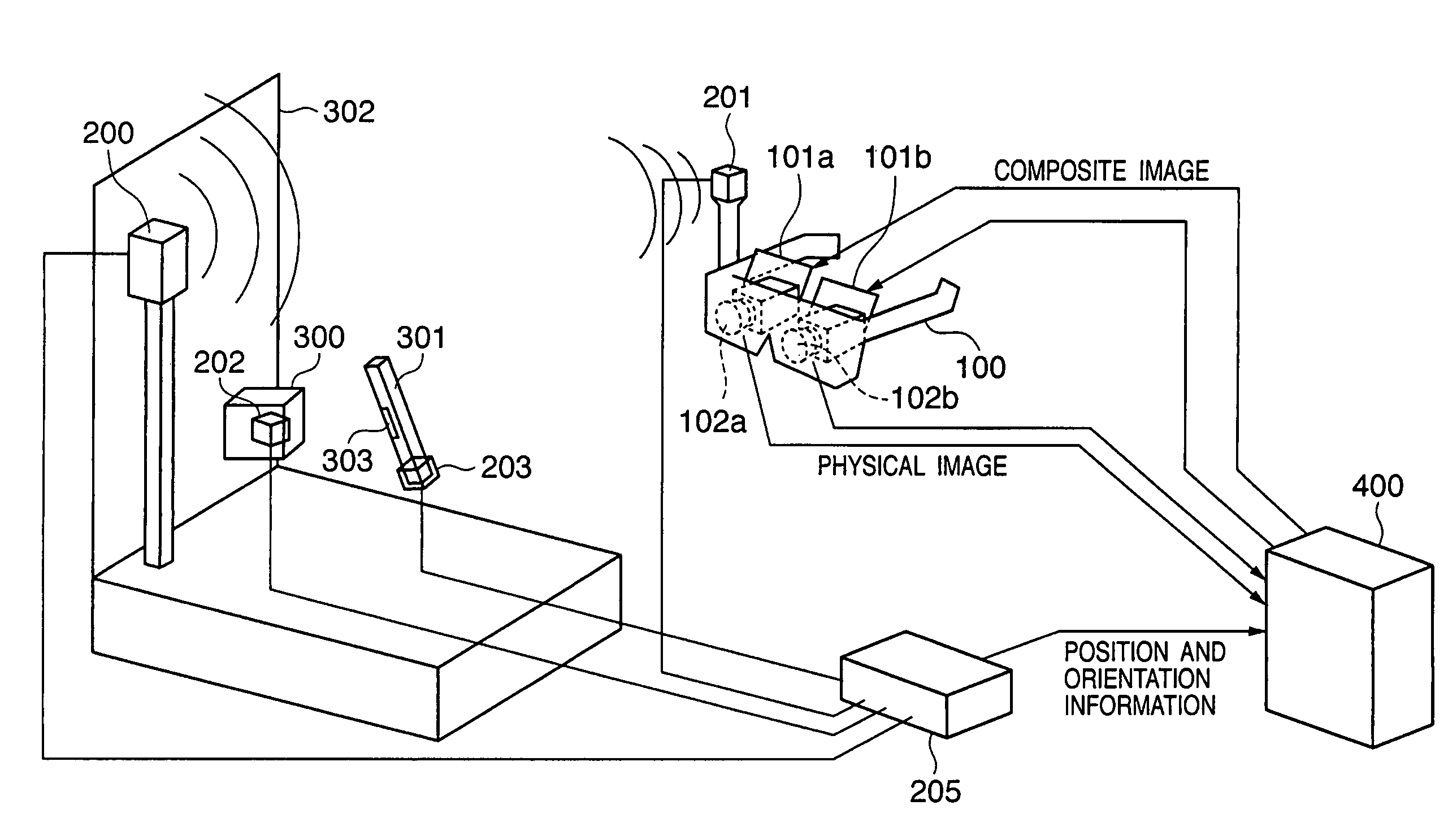
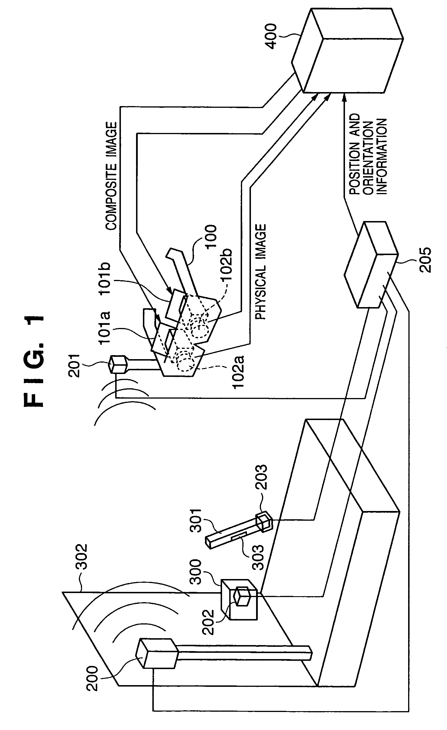
FIG. 1 is a view showing the outer appearance of a system according to the first embodiment, which provides, to the observer, an MR space obtained by superimposing a virtual space on a physical space and allows the observer to browse and manipulate a virtual object on the virtual space.
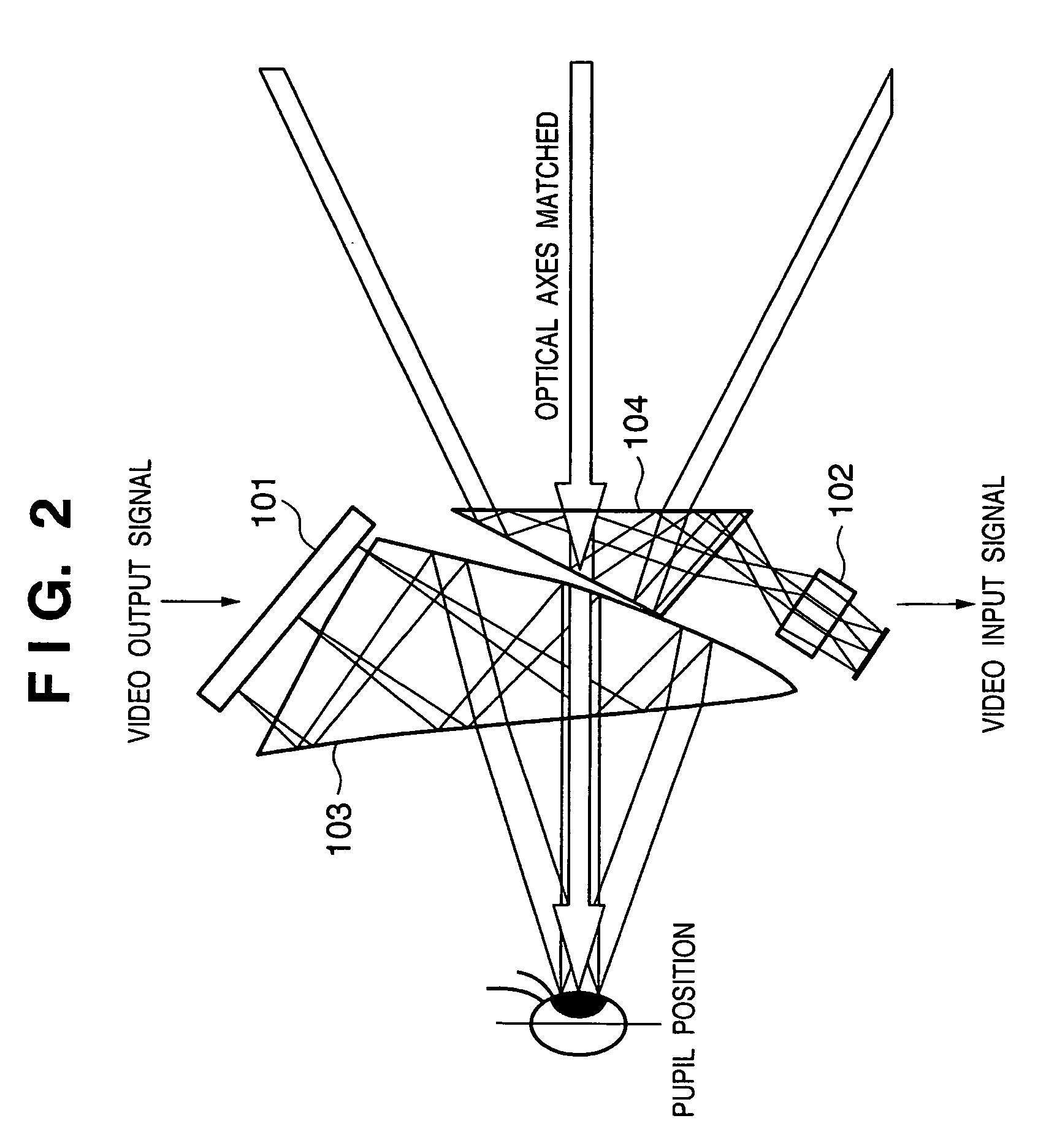
Referring to FIG. 1, reference numeral 200 denotes a transmitter which generates a magnetic field. Reference numeral 100 denotes a head mounted display (to be referred to as an HMD hereinafter), which is mounted on the head of the observer to present images formed by combining a physical space and virtual space to positions before eyes. The HMD 100 comprises cameras 102a and 102b, display devices 101a and 101b, and a magnetic receiver 201.
Cameras 102a and 102b respectively continuously capture the physical space which is seen from the right and left eyes of the observer who wears the HMD 100 on the head, and output the captured frame images to a computer 400. In the following description, cameras 102a...
second embodiment
In the first embodiment, upon setting the control panel light source on the virtual space, there are two cases, i.e., a case wherein the “irradiation direction from the control panel light source is fixed with respect to the control panel” and a case wherein the “irradiation direction from the control panel light source is fixed with respect to the pointing device 301 (tool model)”. However, when the “irradiation direction from the control panel light source is fixed with respect to the control panel”, the shadow of the pointing device 301 may become a spot, or the shadow may hide behind the pointing device 301 when viewed from the observer. When the “irradiation direction from the control panel light source is fixed with respect to the pointing device 301 (tool model)”, the shadow of the pointing device 301 does not often drop on the control panel depending on the tilt of the pointing device 301.
Therefore, in this embodiment, the position and orientation of the control panel light ...
third embodiment
In the description of the first and second embodiments, it is possible to render the shadow of the pointing device which is easy to recognize by using the control panel virtual light illumination determination method. However, depending on the relative position and orientation relationship among the control panel, the pointing device, and the head of the observer, the shadow of the pointing device dropping on the control panel is often difficult to see.
In this embodiment, a method of setting a plurality of light sources so as to form the shadow of the pointing device to be easier to recognize on the control panel will be described.
FIG. 13 shows the control panel and an example of the rendering result of the shadows of the pointing device by three light sources.
In this embodiment, a plurality of control panel light sources are evenly laid out with respect to the plane of the control panel. FIG. 14 shows a plurality of directional light ray directions when the plane of the control pan...
PUM
 Abstract
Description
Claims
Application Information
 - R&D
- Intellectual Property
- Life Sciences
- Materials
- Tech Scout
- Unparalleled Data Quality
- Higher Quality Content
- 60% Fewer Hallucinations
Browse by: Latest US Patents, China's latest patents, Technical Efficacy Thesaurus, Application Domain, Technology Topic, Popular Technical Reports.
© 2025 PatSnap. All rights reserved.Legal|Privacy policy|Modern Slavery Act Transparency Statement|Sitemap|About US| Contact US: help@patsnap.com


