
Multi-channel optical rotary transmission device with high return loss

a transmission device and optical rotary technology, applied in electromagnetic transmission, electromagnetic transmitters, transmission, etc., can solve the problems of relatively low return loss, relatively strong reflection of transmitted light inside the rotating data transmission device, and low return loss, so as to improve the optical return loss of the arrangement

Active Publication Date: 2011-06-21
SCHLEIFRING & APPBAU
View PDF77 Cites 5 Cited by
  • Summary
  • Abstract
  • Description
  • Claims
  • Application Information

AI Technical Summary

Benefits of technology

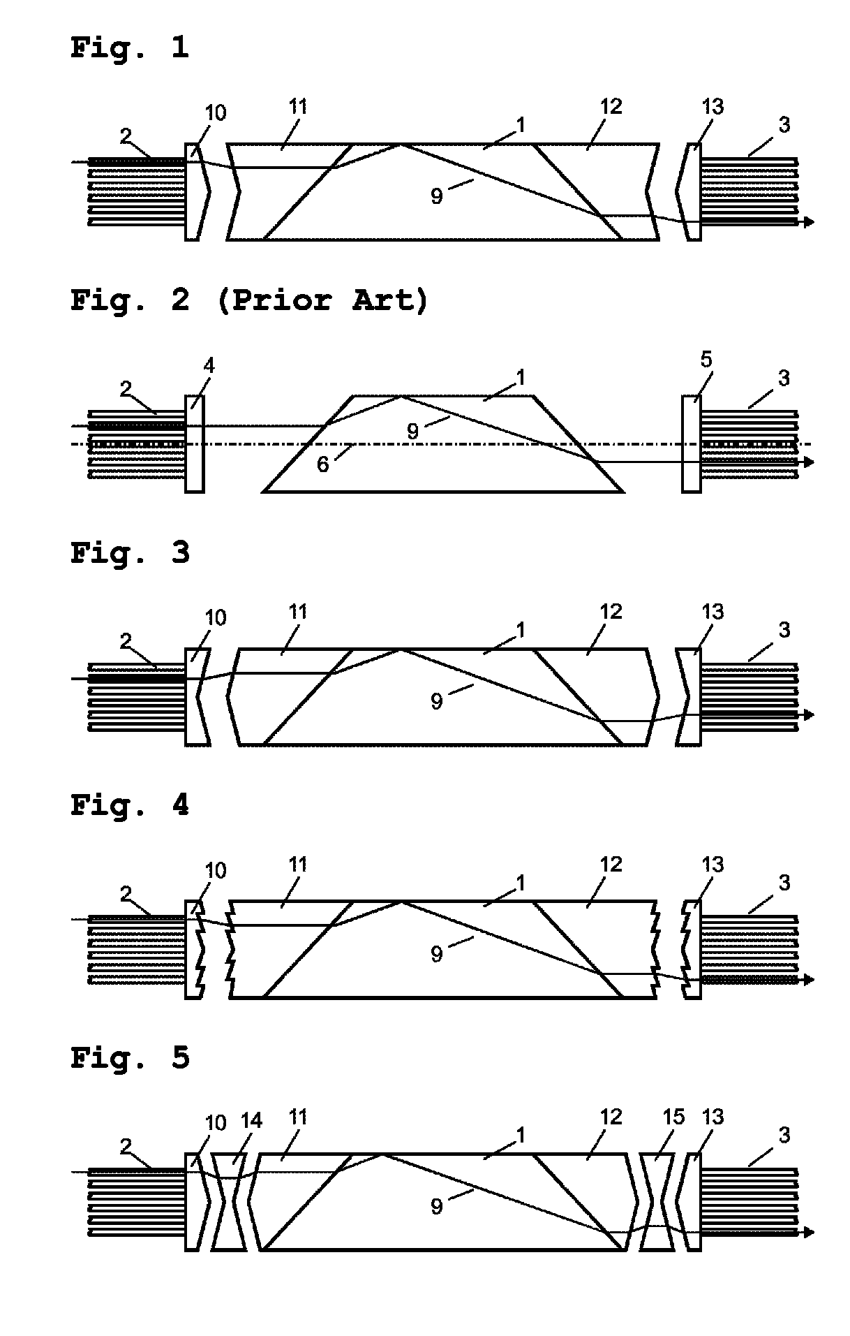
This configuration significantly reduces optical return loss by avoiding perpendicular surfaces and compensating for refractive index variations within the device, allowing for efficient multi-channel optical signal transmission with reduced reflections.

Problems solved by technology

A disadvantage of this is a partial reflection of the light from the perpendicular interface, so that at least a part of the light is coupled back into the light guide.
This results in a relatively low return loss.
Once again, the parallel light entry and light exit faces that cause a relatively low return loss are of disadvantage.
A disadvantage of the known prior art is that relatively strong reflections of the transmitted light occur inside the rotating data transmission device.

Method used


Image

  • Multi-channel optical rotary transmission device with high return loss
  • Multi-channel optical rotary transmission device with high return loss
  • Multi-channel optical rotary transmission device with high return loss

Examples


Embodiment Construction

[0019]The device in accordance with the invention comprises two collimator arrangements 4, 5 that are disposed to rotate relative to each other about a rotation axis 6. An optical path for transmission of light is present between the first collimator arrangement 4 and the second collimator arrangement 5 disposed to be rotatable relative thereto. In this optical path at least one derotating element is present, for example a Dove prism 1, which ensures an imaging of the light emitted from the first collimator arrangement 4 on the second collimator arrangement 5, and similarly also in the opposite direction, independently from the rotational movement between the two collimators. For this, the Dove prism is rotated at one half of the angular velocity of the rotation of the first collimator arrangement 4 and the second collimator arrangement 5.

[0020]Each of the collimator arrangements 4, 5 comprises at least one collimator and also at least one means for supporting the at least one colli...


PUM


Abstract

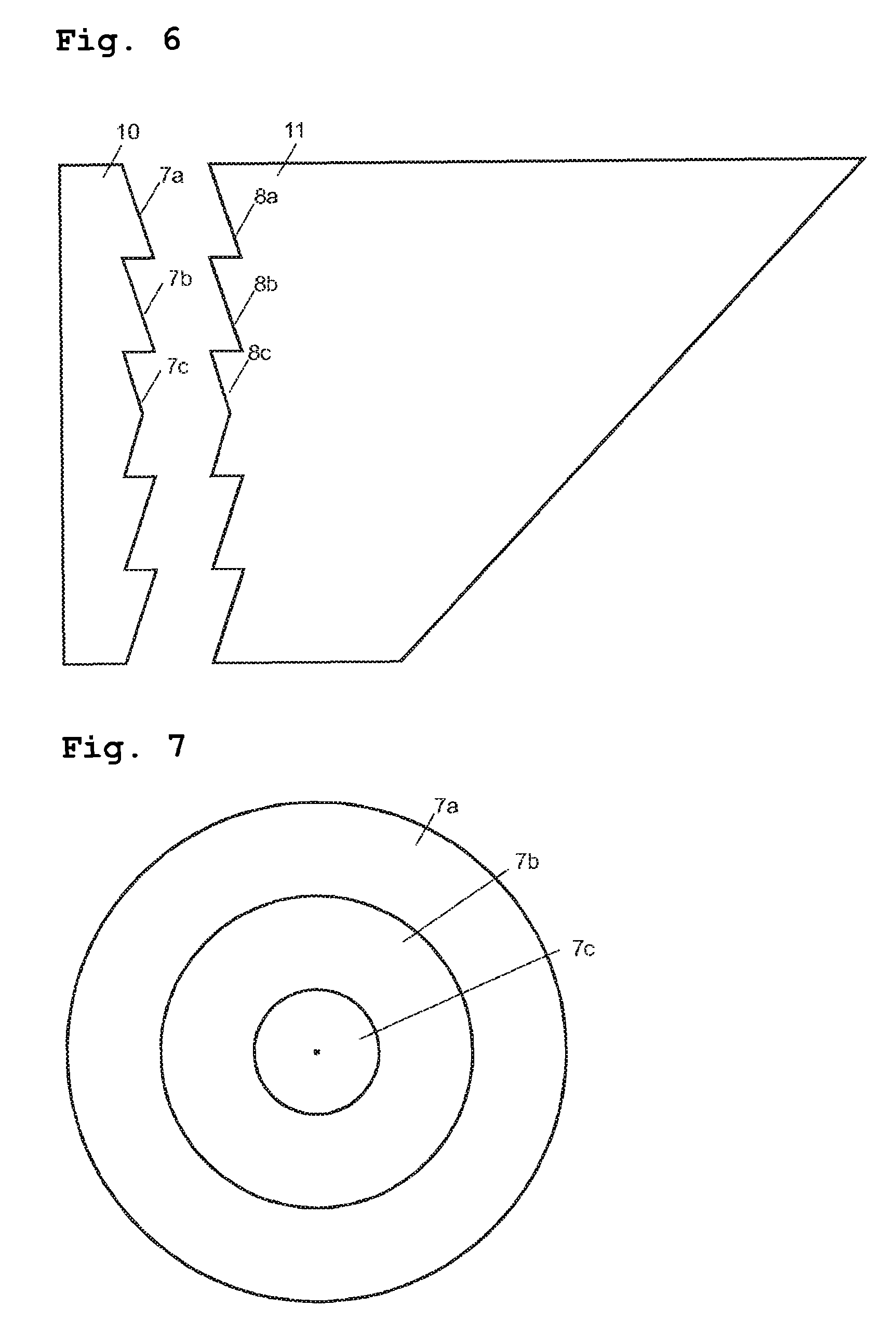
An optical rotating data transmission device comprises a first collimator arrangement for coupling-on first light-waveguides, and a second collimator arrangement for coupling-on second light-waveguides, which is supported to be rotatable relative to the first collimator arrangement about a rotation axis. A Dove prism is provided between the collimator arrangements as a derotating element. Furthermore, the collimator arrangements pre provided with adapter elements having rotationally symmetrical conical faces. Prism adapter elements are disposed on the end faces of the Dove prism and have prism adapter elements on the sides facing the collimator arrangements. These also have rotationally symmetrical conical faces with a surface configuration that is inverse to that of the adapter elements of the collimator arrangements.

Description

CROSS REFERENCE TO RELATED APPLICATIONS[0001]This United States patent application claims priority from German application No. 10 2006 062 335.5 filed on Dec. 22, 2006 (now abandoned) and pending German application No. 10 2007 013 923.5 filed on Mar. 20, 2007.BACKGROUND OF THE INVENTION[0002]1. Field of the Invention[0003]The invention relates to a device for transmitting optical signals between units that are rotatable relative to each other, also termed a rotary coupling or rotary joint. With this, a plurality of optical signals are to be transmitted simultaneously along a plurality of channels.[0004]2. Description of the Prior Art[0005]An optical rotary data transmission device for a plurality of channels, comprising a Dove prism, is disclosed in U.S. Pat. No. 5,568,578. For coupling light into or out of glass fibers, an arrangement comprising a plurality of GRIN lenses is provided. The light is refracted at the light entry faces of the Dove prism in accordance with the refractiv...

Claims


Application Information

Patent Timeline
Patent Type & Authority Patents(United States)
IPC IPC(8): H04B10/12G02B6/34G02B6/26
CPCG02B6/3604
Inventor POPP, GREGORBRAU, JOSEFRANK, MATTHIAS
Owner SCHLEIFRING & APPBAU
Learn More