Apparatus for creating test pattern and calculating fault coverage or the like and method for creating test pattern and calculating fault coverage or the like

a technology of fault coverage and test pattern, applied in the field of apparatus for creating test pattern and calculating fault coverage or the like, can solve the problems of inability to fully improve the logical bridging fault detection test applicable to large-scale lsis, difficult to apply an iddq to detect to detect an abnormal iddq from the measured iddq thereto, and short circuit between the wires

Inactive Publication Date: 2011-06-21
KK TOSHIBA
View PDF4 Cites 4 Cited by
  • Summary
  • Abstract
  • Description
  • Claims
  • Application Information

AI Technical Summary

Benefits of technology

[0034]calculating a detection limit resistance value based on a voltage of the bridging point included in the bridging fault voltage information and the supply current value information and a distribution of logical thresholds of a cell included in the logical threshold information and to which the bridging point is connected, adding information on the detection limit resistance value to the bridging fault voltage information and creating extended bridging fault voltage information;

Problems solved by technology

A bridging fault occurs when foreign matters such as dust are stuck across a pair of signal wires arranged close to each other (hereinafter referred to as a “wire pair”) resulting in a short circuit between the wires.
However, with the advance of process miniaturization, an IDDQ value drastically increases with an LSI operating at high speed in particular, making it difficult to apply an IDDQ to detect to detect an abnormal IDDQ from the measured IDDQ thereto.
However, logical bridging fault detection tests applicable to large-scale LSIs cannot yet be said to have fully improved except simple ones that only handle bridging fault types such as Wired-AND or Wired-OR.
On the other hand, as the fault detection accuracy of a test pattern for a bridging fault detection test, only a certain practical level of accuracy needs to be achieved and even if the accuracy is further improved, the additional effect of the bridging fault detection test tends to reduce.
However, it is extremely difficult to acquire all the above described information and acquisition of information takes an enormous amount of time for a large-scale LSI.
Therefore, generating an effective bridging fault test pattern making full use of the information also takes an enormous amount of time.
However, since these techniques calculate the detection limit resistance value Rc using the gate width of a cell, the calculation expression becomes complicated.
Furthermore, a latest cell library generally includes cells having a complicated configuration such as a composite gate and may not secure sufficient accuracy in a cell library used for an LSI.

Method used


Image

  • Apparatus for creating test pattern and calculating fault coverage or the like and method for creating test pattern and calculating fault coverage or the like
  • Apparatus for creating test pattern and calculating fault coverage or the like and method for creating test pattern and calculating fault coverage or the like
  • Apparatus for creating test pattern and calculating fault coverage or the like and method for creating test pattern and calculating fault coverage or the like

Examples


first embodiment

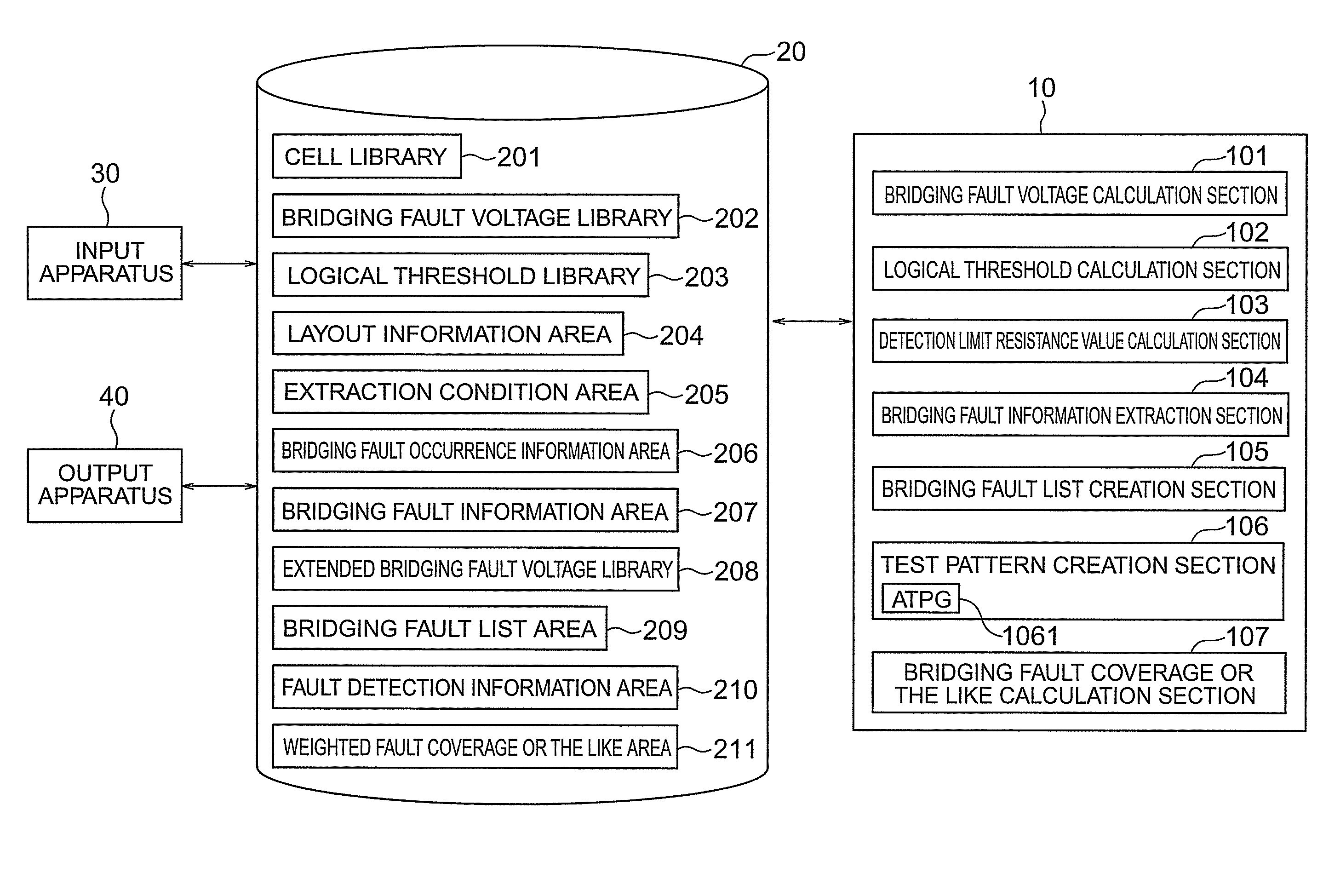
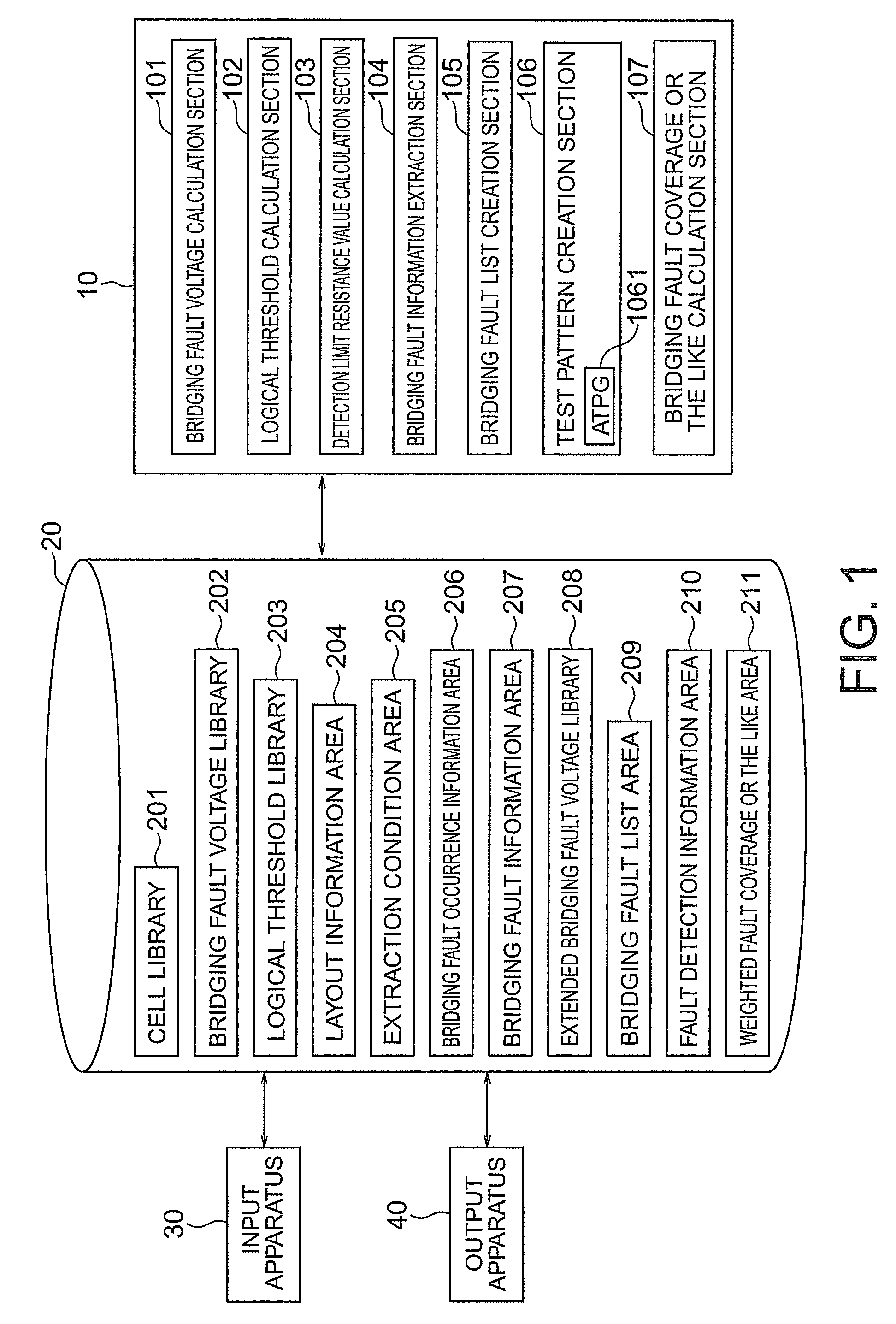
[0073]FIG. 1 shows a schematic configuration of an apparatus for creating a test pattern and calculating a fault coverage or the like according to a first embodiment of the present invention.

[0074]A bridging fault voltage calculation section 101 calculates voltages of short-circuited points assumed on wires derived from arbitrary output terminals of a plurality of cells. A logical threshold calculation section 102 calculates a logical threshold of input terminals of the plurality of cells and creates logical threshold information.

[0075]A detection limit resistance value calculation section 103 calculates a detection limit resistance value of each bridging fault and creates extended bridging fault voltage information.

[0076]A bridging fault information extraction section 104 extracts bridging fault information including signal information on an adjacent wire pair whose inter-wire distance is within a predetermined short distance range and information on a drive cells or the like.

[0077...

second embodiment

[0197]FIG. 19 shows a schematic configuration of an apparatus for creating a test pattern and calculating a fault coverage or the like according to a second embodiment of the present invention.

[0198]A bridging fault voltage / oscillation accuracy or the like calculation section 1901 calculates a voltage of a short-circuited point assumed on an arbitrary output terminal of a plurality of cells. A logical threshold calculation section 1902 calculates logical thresholds of input terminals of a plurality of cells and creates logical threshold information.

[0199]A bridging fault information extraction section 1903 extracts bridging fault information including signal information on an adjacent wire pair whose inter-wire distance is within a predetermined short distance range and information on a drive cell or the like.

[0200]A searching section 1904 detects whether or not the bridging fault pair included in the bridging fault information is a feedback fault. A bridging fault list creation sec...


PUM


Abstract

The method for creating a test pattern and calculating a fault coverage or the like of the present invention is characterized by creating bridging fault voltage information indicating a voltage of a bridging assumed on the wire derived from an output terminal of a cell, calculating a logical threshold of an input terminal of the cell, extracting bridging fault information on an adjacent wire pair, calculating a detection limit resistance value using the logical threshold, adding the detection limit resistance value to bridging fault voltage information, creating extended bridging fault voltage information, creating a bridging fault list including a bridging fault type based on the extended bridging fault voltage information, creating a test pattern based on the bridging fault list, judging whether or not a bridging fault can be detected through this test pattern, creating fault detection information and calculating a weighted fault coverage based on the fault detection information and bridging fault generation information.

Description

CROSS REFERENCE TO RELATED APPLICATION[0001]This application is based upon and claims benefit of priority from the Japanese Patent Application No. 2007-112914, filed on Apr. 23, 2007, the entire contents of which are incorporated herein by reference.BACKGROUND OF THE INVENTION[0002]The present invention relates to an apparatus for creating test pattern and calculating a fault coverage or the like and a method for creating a test pattern and calculating a fault coverage or the like.RELATED ART[0003]With the advance of miniaturization in semiconductor processes and multilayered wiring, the proportion of bridging faults among faults of semiconductor integrated circuits (LSI) is estimated to increase. A bridging fault occurs when foreign matters such as dust are stuck across a pair of signal wires arranged close to each other (hereinafter referred to as a “wire pair”) resulting in a short circuit between the wires.[0004]Conventionally, bridging fault detection tests targeted at bridging...

Claims


Application Information

Patent Timeline
Patent Type & Authority Patents(United States)
IPC IPC(8): G01R31/28
CPCG01R31/31835
Inventor NOZUYAMA, YASUYUKI
Owner KK TOSHIBA
Why Eureka
Try Eureka