Blade sharpener

a blade and guide technology, applied in the field of blade sharpeners, can solve the problems of large and expensive machines not practical for use, the blade and guide of typical grinding wheel sharpening apparatuses are not properly supported, and the blade and guide are more robust and difficult to sharpen. , to achieve the effect of excellent support and enhanced blade li

Inactive Publication Date: 2011-06-28
MESSNER MARVIN
View PDF18 Cites 14 Cited by
  • Summary
  • Abstract
  • Description
  • Claims
  • Application Information

AI Technical Summary

Benefits of technology

[0006]The blade sharpener of the present invention provides a mechanism which is not only designed for accurate blade sharpening, but is especially suited for use both by those which frequently sharpen blades as well as those whose sharpening activities are less frequent. The blade sharpener of the present invention not only provides adjustment in the sharpening angle, but provides excellent support for even large blades and further promotes proper sharpening techniques which enhance blade life.

Problems solved by technology

However, some cutting blades are more robust and more difficult to sharpen.
While these can be sharpened with conventional grinding wheels, these are often large and expensive machines not practical for use by those performing intermittent sharpening tasks.
Moreover, typical grinding wheel sharpening apparatus do not appropriately support the blade and guide the relative movement of the sharpening apparatus along the blade.

Method used


Image

  • Blade sharpener
  • Blade sharpener
  • Blade sharpener

Examples


Embodiment Construction

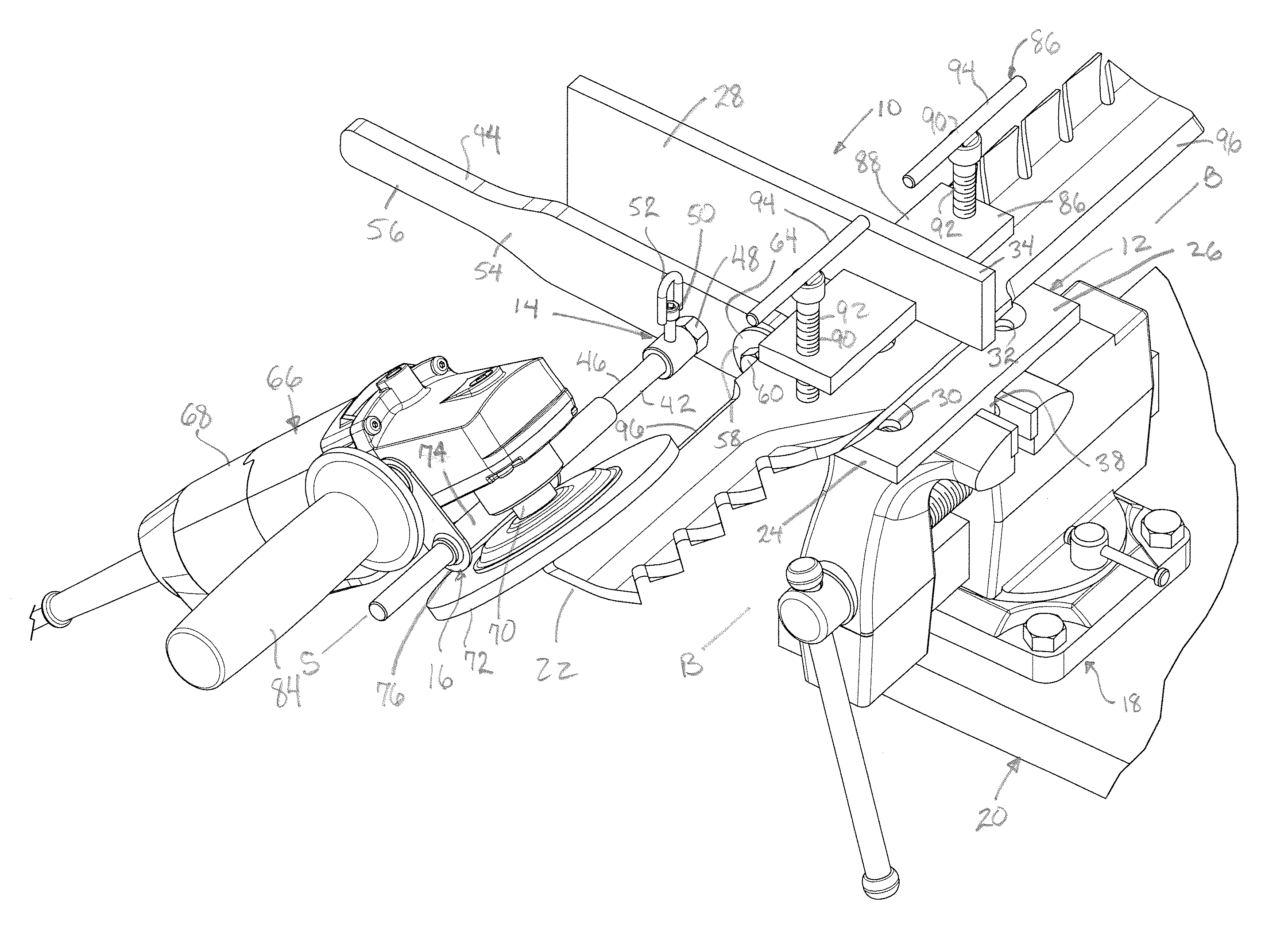
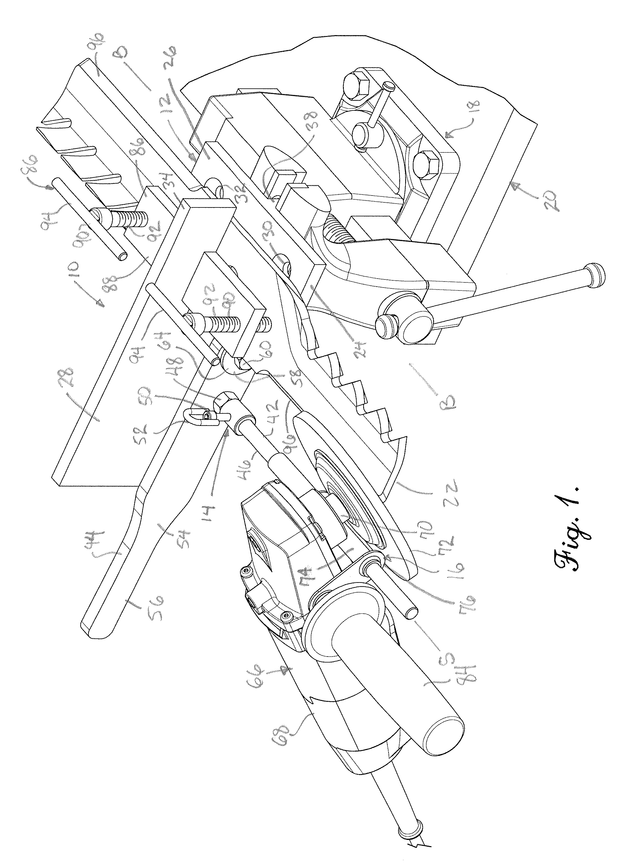
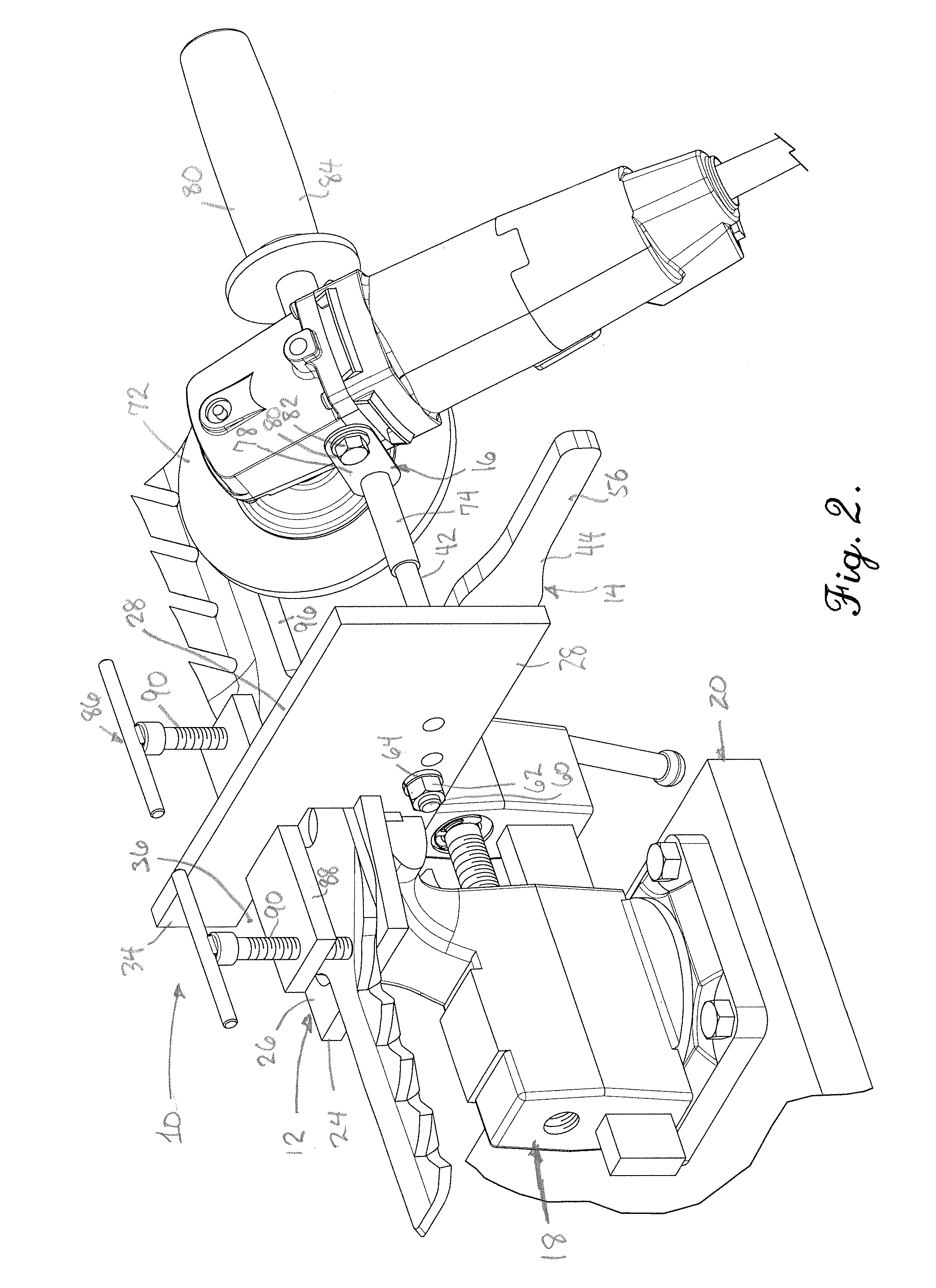
[0018]Referring now to the drawings, an apparatus for use as a blade sharpener 10 broadly includes a blade support 12, a sharpener guide 14, and a sharpener mount 16. The blade sharpener 10 is configured to be held by a vise 18 coupled to a supporting surface 20 as shown in FIGS. 1-3, or alternatively mounted directly to the supporting surface 22 as shown in FIGS. 4 and 5. While the blade sharpener 10 is particularly adapted for sharpening the blade 22 of a rotary lawn mower, it may be appreciated that the blades of other tools having a cutting edge such as, for example, a machete, may also be sharpened by the blade sharpener 10 hereof.

[0019]In greater detail, the blade support 12 is preferably formed of metal such as mild steel and includes a base 24 including a blade receiving surface 26, and a beam 28. The base 24 may be drilled with holes 30 and 32 which may be countersunk. The blade receiving surface 26 is preferably elongated such that its width and depth as seen in FIG. 3 is ...


PUM

PropertyMeasurementUnit
sharpening angleaaaaaaaaaa
cutting angleaaaaaaaaaa
angleaaaaaaaaaa

Abstract

An apparatus useful for sharpening blades includes a blade support, a sharpener guide mounted to the blade support, and a sharpener mount. The sharpener guide includes an elongated guide member defining a sharpening axis extending substantially parallel to a blade axis defined by the blade support. The sharpener mount includes a pivot connector coupled to and complementally configured with the elongated guide member for enabling pivotal movement of the sharpener mount about the sharpening axis and translational movement along the elongated guide member. The sharpener mount may be coupled to a rotary grinder having a grinding wheel, such that the sharpener mount and the grinder may pivot to provide a desired sharpening angle on the blade and move the grinder along the blade while the blade remains in place on the blade support.

Description

BACKGROUND OF THE INVENTION[0001]1. Field of the Invention[0002]The present invention broadly concerns a blade sharpener useful for sharpening the blades of cutting implements, for example, lawn mower blades. More particularly, it is concerned with a blade sharpener which serves as a support for a blade and a guide for a blade sharpening device to move along a cutting edge of a blade.[0003]2. Description of the Prior Art[0004]A variety of different devices are known for sharpening the blades of cutting implements. For example, sharpening stones and files are well known tools which are drawn across a cutting edge of a blade for sharpening. Other sharpening devices include grinding wheels which rotate and used by placing the edge of a cutting implement in engagement with the rotating wheel, and sharpeners typically used with knives or scissors wherein a body acts as a guide and whereby the cutting edge is drawn along a sharpening stone while generally held in a desired angular relatio...

Claims


Application Information

Patent Timeline
Patent Type & Authority Patents(United States)
IPC IPC(8): B24B23/00
CPCB24B3/365B24B23/028B24B23/005
Inventor MESSNER, MARVIN
Owner MESSNER MARVIN
Why Eureka
Try Eureka