Forced-fluid flow ventilating system for rotating electrical machines and rotating electrical machine comprising same

a technology of forced flow and ventilating system, which is applied in the direction of dynamo-electric machines, synchronous generators, structural associations, etc., can solve the problems of unsatisfactory ratio of useful power in comparison with consumed power, high and total mechanical loss of 1.5 kw, so as to reduce mechanical loss and noise level of ventilation system

Active Publication Date: 2011-06-28
VALEO EQUIP ELECTRIC MOTEUR
View PDF26 Cites 8 Cited by
  • Summary
  • Abstract
  • Description
  • Claims
  • Application Information

AI Technical Summary

Benefits of technology

[0015]According to one embodiment, the fan driven by the rotor has a reduced size compared with a fan fixed to the rotor that is to produce a flow rate substantially equal to the total flow rate of the independent fan and the rotor fan of reduced size.
[0016]According to yet another advantageous embodiment of the invention, the ventilation system is characterised in that the reduction in the size of the fan fixed to the rotor constitutes a means of reducing the mechanical losses and the noise level produced by the ventilation system.

Problems solved by technology

Thus, for a rotary electrical machine equipped with a front fan and a rear fan, in the present case for example, there therefore occurs a total mechanical loss of around 1.5 kW.
Another major drawback of the conventional ventilation systems described above is that the ventilation noise level, which appears at around 7000 revolutions per minute (rpm), becomes very high, for example 115 dB at a speed of rotation of 18000 (rpm). FIG. 1 makes it possible to asses, for a given conventional rotary electrical machine, the change in the useful power indicated by curve A and the consumed power indicated by curve B, as a function of the speed of rotation.
This figure shows clearly the unsatisfactory ratio of the useful power in comparison with the consumed power, inherent in the conventional ventilation system using a fan rotationally fixed to the rotor.

Method used


Image

  • Forced-fluid flow ventilating system for rotating electrical machines and rotating electrical machine comprising same
  • Forced-fluid flow ventilating system for rotating electrical machines and rotating electrical machine comprising same
  • Forced-fluid flow ventilating system for rotating electrical machines and rotating electrical machine comprising same

Examples


Embodiment Construction

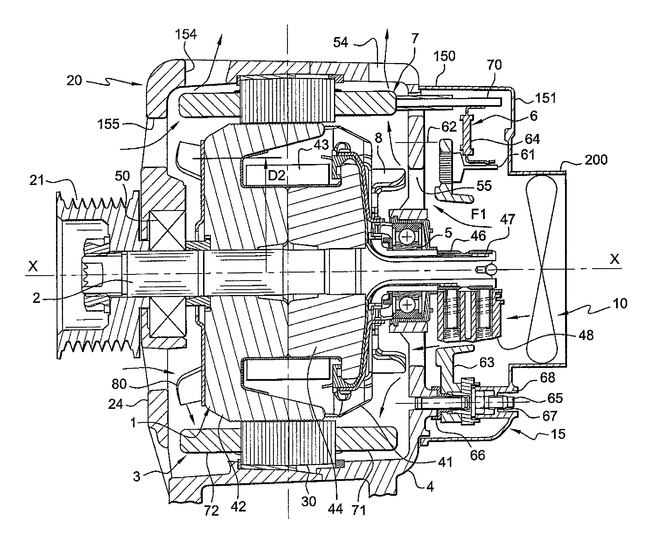
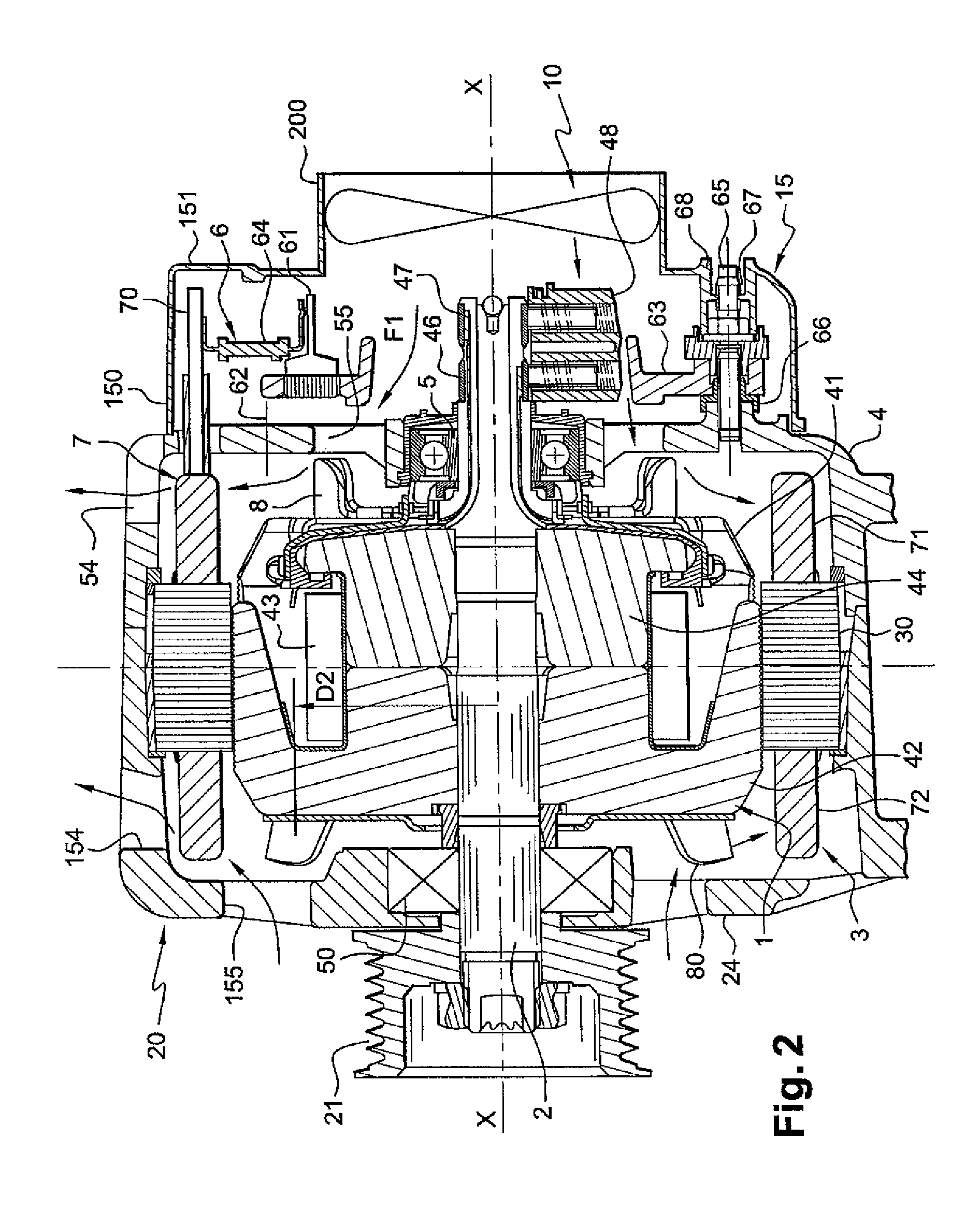
[0038]FIG. 2 illustrates schematically the structure of a rotary electrical machine equipped with a ventilation system according to the invention.

[0039]In this FIG. 2 this machine consists of a multi-face alternator for a motor vehicle with internal ventilation comprising a casing 20 in at least two parts 4, 24 carrying internally a stator 3 surrounding an inducting rotor 1 fixed to a rotor shaft 2. The stator 3 comprises a body 30 carrying a winding 7. The winding 7 passes through the body 30 and extends in axial projection on each side of this body 30.

[0040]The body 30 and the rotor 1 are annular in shape. The two parts 4, 24, referred to respectively as the wheel bearing 4 and front bearing 24, are in FIG. 2 metal or more precisely based on aluminium.

[0041]These bearings 4, 24 have a hollow shape and each have a bottom with a transverse orientation overall extended at its external periphery by a roughly axially oriented rim.

[0042]They have lugs, depicted partially in this FIG. 2,...


PUM


Abstract

The invention concerns a ventilation system for a rotary electrical machine of the type comprising a rotor mounted so as to rotate in a stator and a device for cooling by forced flow of a cooling fluid, such as air, provided with at least one fan fixed to the rotor and an independent fan disposed so as to be decisive for cooling at relatively low speeds of rotation of the rotor.

Description

FIELD OF THE INVENTION[0001]The invention concerns a ventilation system for rotary electrical machines, in particular for motor vehicles, of the type comprising a rotor mounted so as to rotate in a casing carrying a stator surrounding the rotor and a device for cooling by forced flow of a fluid, such as air, provided by at least one fan fixed to the rotor.[0002]The invention also concerns a rotary electrical machine comprising such a ventilation system.BACKGROUND OF THE INVENTION[0003]Ventilation systems of this type are frequently used in the field of rotary electrical machines, in particular in alternators for motor vehicles comprising a casing in at least two parts, referred to as the front bearing and rear bearing. These bearings are provided with an inlet and outlet openings for the circulation of a cooling fluid inside the machine under the action of at least one fan.[0004]More precisely, this fan, fixed to the rotor, creates a flow of cooling fluid, such as air, the flow rate...

Claims


Application Information

Patent Timeline
Patent Type & Authority Patents(United States)
IPC IPC(8): H02K9/04H02K9/06
CPCH02K9/04H02K11/048H02K19/22H02K11/05
Inventor VASILESCU, CLAUDIUFAKES, MICHEL
Owner VALEO EQUIP ELECTRIC MOTEUR
Why Eureka
Try Eureka