Systems and methods for monitoring relief valve drain in hot water Heater

a technology for hot water heaters and drains, applied in flow control, ratio control, electrical beam welding apparatus, etc., can solve the problems of increasing the difficulty of manually detecting a failed valve, wasting a large amount causing the failure of the relief valve to fail, so as to prevent the potential waste of significant amounts of water and energy, prevent explosion or other damage to the water heater or surrounding structures, and prolong the life of the water heater

Inactive Publication Date: 2011-06-28
GREEN DRAIN
View PDF49 Cites 37 Cited by
  • Summary
  • Abstract
  • Description
  • Claims
  • Application Information

AI Technical Summary

Benefits of technology

[0008]Should the relief valve fail to open, the system restricts an energy flow to the water heater, to thereby prevent an explosion or other damage to the water heater or surrounding structures. This extends the life of the water heater by allowing a user to simply replace the failed relief valve rather than the water heater itself. In addition, by monitoring a flow of water to the drain pipe, the system can detect if the relief valve is stuck in an open position. In this manner, the system can advantageously prevent the potential waste of significant amounts of water and energy resulting from the failed relief valve.

Problems solved by technology

However, the relief valves often develop calcium, limestone and other mineral deposits over time that can cause the relief valves to fail.
However, such monitors fail to detect a situation in which the relief valve is stuck in an open position, which can lead to flooding and wasting a large amount of water and energy before the problem is detected.
This is especially problematic since many relief valves expel water out of the sight of users, which increases the difficulty of manually detecting a failed valve.

Method used


Image

  • Systems and methods for monitoring relief valve drain in hot water Heater
  • Systems and methods for monitoring relief valve drain in hot water Heater
  • Systems and methods for monitoring relief valve drain in hot water Heater

Examples


Embodiment Construction

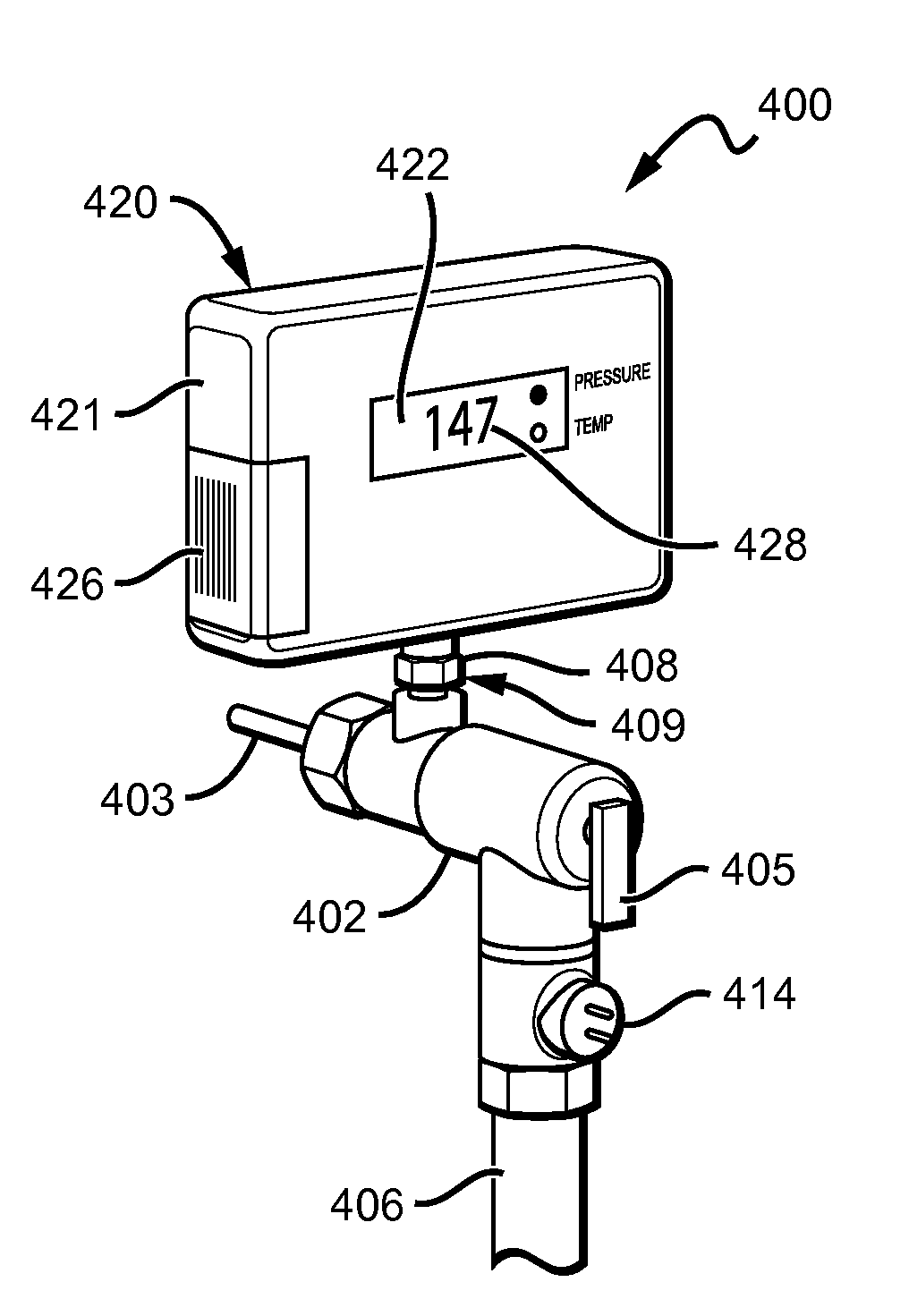
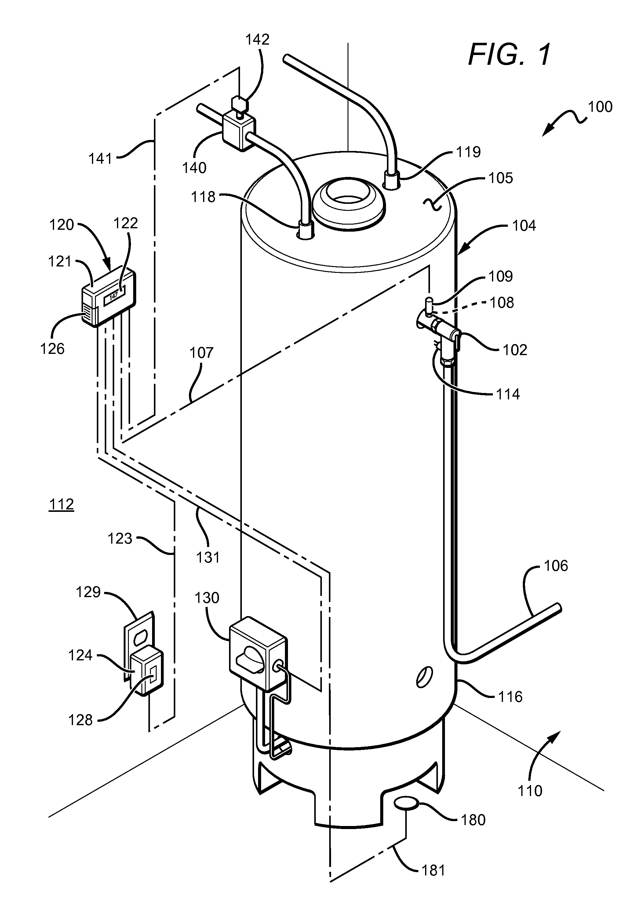
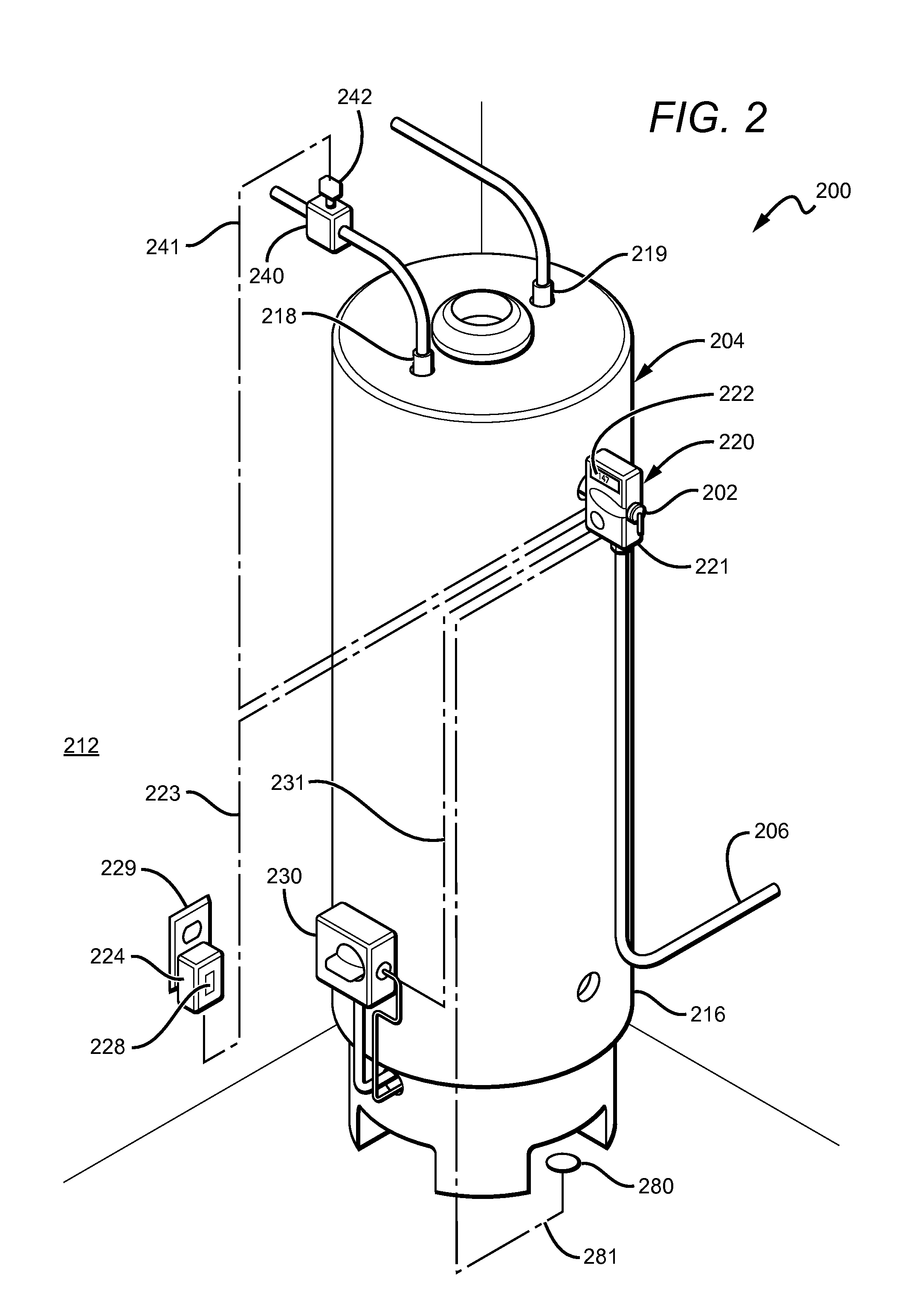
[0022]In FIG. 1, system 100 monitors a status of a relief valve 102 coupled to a water heater 104 of a residential, commercial, or other structure 110. The relief valve 102 is disposed between the water heater 104 and a drain pipe 106. Although the relief valve 102 is shown separately housed from the water heater 104, it is contemplated that the relief valve 102 could be integrated into the water heater 104.

[0023]The relief valve 102 can be configured to open when a pressure or temperature exceeds predetermined thresholds. In some embodiments, the relief valve can be configured to open when the pressure in the valve exceeds 150 psi or the temperature exceeds 210° F. However, the threshold values could be varied depending on the configuration of the relief valve or the water heater.

[0024]Any commercially suitable valve could be used including, for example, needle valves, ball valves, gate valves, poppet valves, plug valves, globe valves, butterfly valves, and diaphragm valves. An exe...


PUM

PropertyMeasurementUnit
temperatureaaaaaaaaaa
pressureaaaaaaaaaa
temperatureaaaaaaaaaa

Abstract

A system is disclosed that advantageously monitors a status of a relief valve coupled to a water heater or other pressure vessel. By monitoring the relief valve, the system can limit the energy and water wasted resulting from the relief valve's failure. The system can have first and second sensors that monitor a temperature and pressure within the relief valve, and a water flow from the relief valve, respectively. If the temperature or pressure within the relief valve exceeds predetermined thresholds, or a water flow from the relief valve continues for greater than a predetermined interval, the system can restrict a flow of gas, electric current, or water to the water heater.

Description

[0001]This application is a continuation-in-part of U.S. Utility application having Ser. No. 10 / 668,897 filed on Sep. 23, 2003, which is a continuation-in-part of U.S. Pat. No. 6,766,835 filed on Sep. 23, 2002. This and all other extrinsic materials discussed herein are incorporated by reference in their entirety. Where a definition or use of a term in an incorporated reference is inconsistent or contrary to the definition of that term provided herein, the definition of that term provided herein applies and the definition of that term in the reference does not apply.FIELD OF THE INVENTION[0002]The field of the invention is water heaters.BACKGROUND[0003]Hot water heaters and other pressure vessels typically have a relief valve that opens to expel fluid when a temperature or pressure within the water heater exceeds predetermined levels. In this manner, explosions can be prevented by reducing the volume of fluid in the water heater, which reduces the temperature and pressure within the...

Claims


Application Information

Patent Timeline
Patent Type & Authority Patents(United States)
IPC IPC(8): G05D11/00
CPCF17D5/02F24D19/082G06Q40/08F24H9/2021F24H9/16Y10T137/1353Y10T137/1516F24H15/269F24H15/45F24H15/238F24H15/355F24H15/242F24H15/395F24H15/486F24H15/31F24H15/223
Inventor FIMA, GIOVANNI
Owner GREEN DRAIN
Why Eureka
Try Eureka