Scanning projection apparatus with phase detection and compensation

a projection apparatus and phase detection technology, applied in the field of scanning projection displays with phase detection and compensation, can solve the problems of projected image pixels being displaced and distorted, and achieve the effects of reducing inherent image defects

Active Publication Date: 2011-07-05
AURISE INVESTMENT CO LTD
View PDF3 Cites 25 Cited by
  • Summary
  • Abstract
  • Description
  • Claims
  • Application Information

AI Technical Summary

Benefits of technology

[0007]The projection apparatus according to the present invention includes a beam scanner having a reflective surface that reflects and scans a light beam to form a two dimensional image field. The light beam is scanned bi-directionally in the horizontal direction. The light beam may be generated by a plurality of light sources consisting of semiconductor lasers and / or solid state lasers to have wavelengths of red, green and blue colors aligning into a single path. In order to reduce inherent image defects such as pinched scan lines and higher brightness due to returning of scanning motions at the extremes of the scan span, the light beam is switched off in the perimeter of the image field which is defined as dark field for explanation purpose in the present invention. Thus, the image field consists of an active image field for projecting image and a dark field for reducing inherent image defects. A sensor capable of detecting the scanned light beam is disposed outside the active image field but near the vertical extreme of with at least part of its sensing area inside the dark field, and a horizontal scan line, “feedback scan line” is generated by switching on the light beam of selected wavelength within specific period of time to shine on the sensor once per image frame. The phase difference between the actual and the predicted positions of the scanned beam can be determined based on detection of the electrical signals received from the sensor and reference timing of initiating the feedback scan line. Modulation of light beam to form image pixels at desired location can then be synchronized with the scanning motion of the light beam. If the beam scanner is malfunctioned in vertical scanning, the feedback scan line will not sweep over the sensor since the sensor is positioned near the vertical extreme of the image field. If the beam scanner is malfunctioned in horizontal scanning, the feedback scan line will not sweep over the sensor in a periodic fashion. Thus, the sensor along with the feedback scan line is capable of detecting the malfunction of the beam scanner in both the horizontal and the vertical scanning motions.

Problems solved by technology

The projected image pixels will become displaced and distorted if the phase difference between the timing of modulating the light beam and the position of the scanned light beam is not compensated correctly.

Method used


Image

  • Scanning projection apparatus with phase detection and compensation
  • Scanning projection apparatus with phase detection and compensation
  • Scanning projection apparatus with phase detection and compensation

Examples


first embodiment

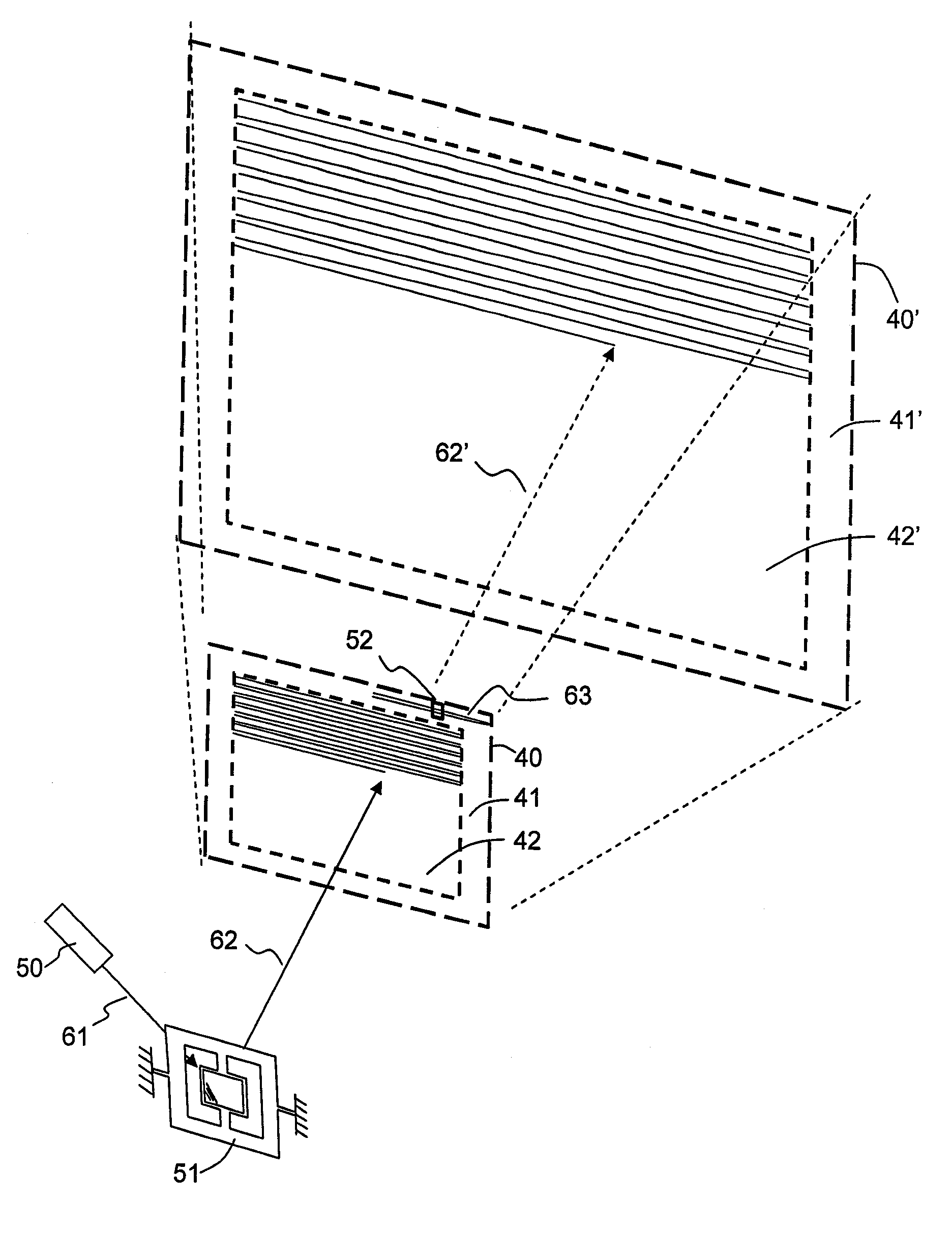
[0031]FIG. 4 illustrates a perspective view of a projection apparatus according to the present invention. A light beam 61 generated by a light source 50 is deflected about two deflection axes of a beam scanner 51 in back and forth motion to project and scan over a two dimensional image field 40 inside the projection apparatus. Although the light beam, as depicted in FIG. 4, is represented by a single beam 61, the light source 50 may consist of a plurality of semiconductor lasers and / or solid state lasers to generate light beams of wavelengths of red, green and blue colors which are aligned into a single light path, and the beam scanner 51, represented as a single beam scanner with two orthogonal deflection axes, may be replaced by two single axis beam scanners with the first beam scanner provides horizontal scanning and the second beam scanner provides vertical scanning of the light beam 62. The horizontal deflection of the light beam 62 is in sinusoidal and bidirectional motion, fo...

second embodiment

[0043]FIG. 10 shows a perspective view of a projection apparatus consisting of a light source 250, a modulation means (not shown) for modulating the intensity of the light beam 261, beam scanners 251A, 251B and a sensor 252 positioned at a distance from the beam scanners 251A, 251B according to the present invention. The light beam 261 generated by a light source 250 is deflected by a first beam scanners 251A to scan horizontally then deflected by a second beam scanner 251B to scan vertically in order to project and scan over a two dimensional image field 240. The image field 240 is divided in to a dark field 241 by switching off the light beam in the perimeter of the image field 240 and an active image field 242 for displaying projected image. Although the display apparatus according to FIG. 10 uses two single axis beam scanners 251A, 251B, a dual axis beam scanner with its deflection axes arranged in orthogonal directions may be used to replace the two single axis beam scanners 25...


PUM


Abstract

A scanning projection apparatus for displaying image comprises a light source for generating a light beam, a beam scanner which deflects the light beam to project a two dimensional image field, a modulation means for modulating the intensity of the light beam, and a sensor to detect the scanned light beam. The light source may consist of a plurality of semiconductor lasers and / or solid state lasers to generate light beams with wavelengths of red, green and blue colors aligned into a single light path. The image field is divided into an active image field for displaying image and a dark field in the perimeter of the image field wherein the light beam is switched off to reduce inherent image defects. The sensor is positioned outside the active image field to detect a scan line once per image frame to eliminate image distortion due to phase difference between the actual and the predicted positions of the scanned beam, and to detect both the horizontal and the vertical scanning operations of the beam scanner for safety precaution.

Description

BACKGROUND OF THE INVENTION[0001]The present invention relates generally to scanning projection apparatuses and more particularly relates to light beam scanning projection displays with phase detection and compensation between the timing of modulating the light beam and the position of the scanned light beam.[0002]In a scanning projection display, a collimated light beam is deflected about two orthogonal axes to move across an image field by either one beam scanner with bi-axial scanning capability or by two single axis beam scanners with their scan axes aligned perpendicular to each other. An image field can be established by sweeping the light beam either in raster pattern or in Lissajous pattern. Images, texts or patterns can be formed over the image field by determining light beam position and modulating the power of the light beam to form desired image pixels according to the received image or video information.[0003]In order to make a compact image projection system, micromech...

Claims


Application Information

Patent Timeline
Patent Type & Authority Patents(United States)
IPC IPC(8): G03B21/14
CPCH04N9/3129H04N9/317H04N9/3194
Inventor HUNG, CHANG-LILIN, TA-WEI
Owner AURISE INVESTMENT CO LTD
Why Eureka
Try Eureka