Catheter and method of manufacturing same

a technology of catheter and manufacturing method, which is applied in the field of catheter, can solve the problems of affecting the required property, affecting the proportion, and reducing the use effect of the catheter, so as to achieve good pushability, high flexibility, and sufficient stability

Inactive Publication Date: 2011-07-05
ABBOTT INT ENTERPRISES LTD
View PDF22 Cites 40 Cited by
  • Summary
  • Abstract
  • Description
  • Claims
  • Application Information

AI Technical Summary

Benefits of technology

[0009]It is an object of the present invention to provide a catheter having an especially high flexibility at its distal end portion, but also a sufficient stability for achieving a good pushability.
[0010]The present invention discloses a catheter and a method for manufacturing same, which provides improved mechanical properties of the tip portion. Preferably, the catheter of the present invention has an entry profile of the catheter as small as possible in order to penetrate narrow stenoses. Moreover, the catheter of the present invention preferably has a tip portion with a minimum entry profile but that is mechanically stable, and featuring a continuously increasing diameter, but being flexible and having a homogenous transition into the balloon cone.
[0012]The above arrangement guarantees a nearly optimum combination of flexible tip and high pushability.

Problems solved by technology

However, the soft tip of this catheter is achieved by a material transition to a material of lesser stability.
This means that the complete tip is made of the soft material, resulting in the problem that this portion tends to bend.
A possible result thereof is a deformation of the tip, which may lead to a constriction of the inner lumen or a permanent deformation.
In case the complete catheter tip, as that of the U.S. Pat. No. 4,782,834, is formed of a soft material, in particular this required property is negatively affected.
When pushing the catheter tip, same can be deformed reversibly or irreversibly and therefore also an entangling at the guide wire can occur (friction).

Method used


Image

  • Catheter and method of manufacturing same
  • Catheter and method of manufacturing same

Examples


Embodiment Construction

[0019]Selected embodiments of the present invention will now be explained with reference to the drawings. It will be apparent to those skilled in the art from this disclosure that the following descriptions of the embodiments of the present invention are provided for illustration only and not for the purpose of limiting the invention as defined by the appended claims and their equivalents.

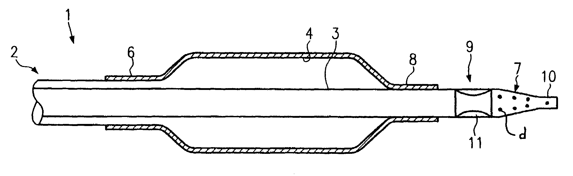
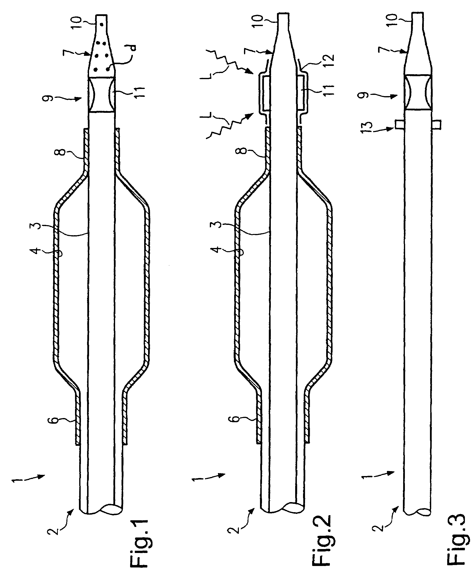
[0020]Referring initially to FIG. 1, a distal end of a catheter 1 is illustrated in accordance with a preferred embodiment of the present invention. The catheter 1 basically comprises a customarily formed catheter shaft portion 2 with its distal end 3 having a balloon 4 formed thereon in a conventional manner. The balloon 4 has a proximal end 6 and a distal end 8 arranged on the catheter shaft portion 2.

[0021]The catheter shaft portion 2 has a catheter tip portion 7 being part of the catheter shaft portion 2 and protruding beyond the distal end 8 of the balloon 3. The catheter tip portion 7 is for ...


PUM

PropertyMeasurementUnit
diameteraaaaaaaaaa
flexibleaaaaaaaaaa
flexibilityaaaaaaaaaa

Abstract

A catheter basically has a catheter shaft in which a catheter tip of which is provided with a joint made of a material which is more flexible than the material of the catheter shaft. The joint is disposed between the distal end of the catheter shaft and the distal end of the catheter tip. The front end consists of a material being the same or more rigid than that of the catheter shaft.

Description

BACKGROUND OF THE INVENTION[0001]1. Field of the Invention[0002]The present invention generally relates to a catheter as well as a method for producing same.[0003]2. Background Information[0004]For an expansion of a stenosis in body vessels or body hollows, catheter arrangements are used nowadays which comprise an expandable balloon at their distal ends. A stent may additionally be crimped on the expandable balloon, which can be placed in the stenosis for stabilizing the vascular wall. The catheter arrangement is guided to the constricted position in the patient's body with the help of a guiding wire. The stenosis is then expanded by expanding the balloon or the crimped stent is placed in the stenosis, respectively.[0005]A catheter having a soft tip is disclosed in U.S. Pat. No. 4,782,834. However, the soft tip of this catheter is achieved by a material transition to a material of lesser stability. This means that the complete tip is made of the soft material, resulting in the probl...

Claims


Application Information

Patent Timeline
Patent Type & Authority Patents(United States)
IPC IPC(8): A61M25/00A61F2/958
CPCA61M25/1036A61M25/0054A61M2025/1093
Inventor QUINT, BODO
Owner ABBOTT INT ENTERPRISES LTD
Why Eureka
Try Eureka