Low profile modular electrical connectors and systems

a modular, electrical connector technology, applied in the direction of coupling device connection, electrical discharge lamp, coupling device details, etc., can solve the problems of loosened contacts or other metal components such as connector screws, adversely affecting electrical characteristics, and negative effects of joule effect, so as to improve air flow, improve electrical characteristics, and reduce the effect of joule

Active Publication Date: 2011-07-12
MOLEX INC
View PDF33 Cites 38 Cited by
  • Summary
  • Abstract
  • Description
  • Claims
  • Application Information

AI Technical Summary

Benefits of technology

[0008]One aspect or embodiment of the invention relates to improved power connectors that have an insulative housing. These housed power connectors have improved and lower. profiles, typically 30% less than commercial housed power connectors with similar power performance. The improved power connectors can include plug connectors and receptacle connectors for mating with each other or other components. The power connector, the receptacle connector or both may comprise two uncoupled contacts seated in cavities in the housing. The contacts have exposed surfaces to dissipate heat resulting from Joule effects, and the cavities are constructed with openings and / or spacings to improve air flow in one or more of the top, bottom, bottom and / or rear of the connector cavities. Improved airflow permits higher current density without unacceptable temperature rise and contributes to providing power connectors that have a low profile with no sacrifice of quality or power handling capabilities.
[0009]In another aspect or embodiment, the use of uncoupled walls eliminates a bridging structure that is used in some prior art approaches to couple and hold two contact walls in position relative to one another. The bridging structure typically needs space on the topside of the contact walls adding to the connector height and profile. Eliminating the space required when a bridging structure is included contributes to a lower connector profile.
[0010]According to another aspect or embodiment, the uncoupled contacts can employ small barbs on the sides of the contacts to assist in holding the contacts in place. According to one approach, a barb is positioned on a side, such as near the bottom of a contact to ride on a shoulder of the housing and lock in the contact vertically. According to another approach, a barb near the top of a contact locks the contact into a housing channel to lock in the contact horizontally. Each barb adds little if anything to connector profile. Typically both barb arrangements will be used to provide secure positioning in two dimensions.
[0011]According to a further aspect or embodiment, the mating sections of the contacts for the plug connector form a blade structure, and the mating sections of the contacts for the receptacle connector typically have multiple contact beams for parallel path current flow to minimize resistance and heat generation in order to aid in employing higher current densities. The multiple contact beams form a receiving section that has camming portions for blade entrance and restriction portions for tight blade contact.
[0012]In accordance with another aspect or embodiment, and for ease of mating and facilitating of modular assemblies, one mating connector can have guide posts and the other mating connector can have guide apertures to receive the guide posts. The guide posts and apertures can be placed on top of the connectors which typically preserves board space or can be placed the side of the connectors for enhanced air flow.

Problems solved by technology

Increasing current density can contribute to reducing the size of a power connector, but heat generated by the Joule effect can have negative effects.
The heat can cause a temperature rise of the contacts that adversely affects electrical characteristics and expands the contacts.
With temperature cycling over time, the expansion effects can lead to loosened contacts or other metal components such as connector screws.
The bridging elements take up space, restrict air flow and hinder flexible use of contacts.

Method used


Image

  • Low profile modular electrical connectors and systems
  • Low profile modular electrical connectors and systems
  • Low profile modular electrical connectors and systems

Examples


Embodiment Construction

[0038]As required, detailed embodiments of the present invention are disclosed herein; however, it is to be understood that the disclosed embodiments are merely exemplary of the invention, which may be embodied in various forms. Therefore, specific details disclosed herein are not to be interpreted as limiting, but merely as a basis for the claims and as a representative basis for teaching one skilled in the art to variously employ the present invention in virtually any appropriate manner.

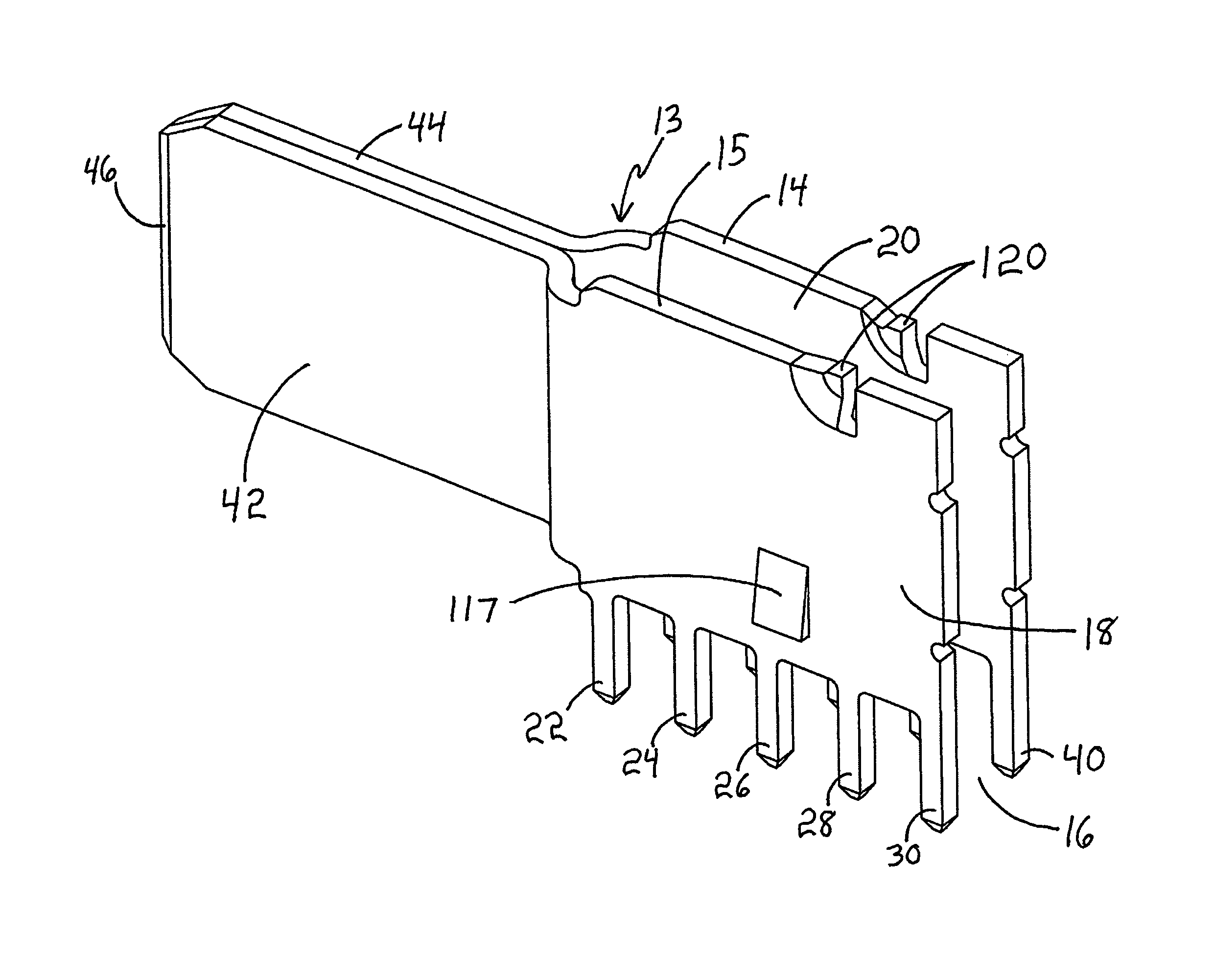
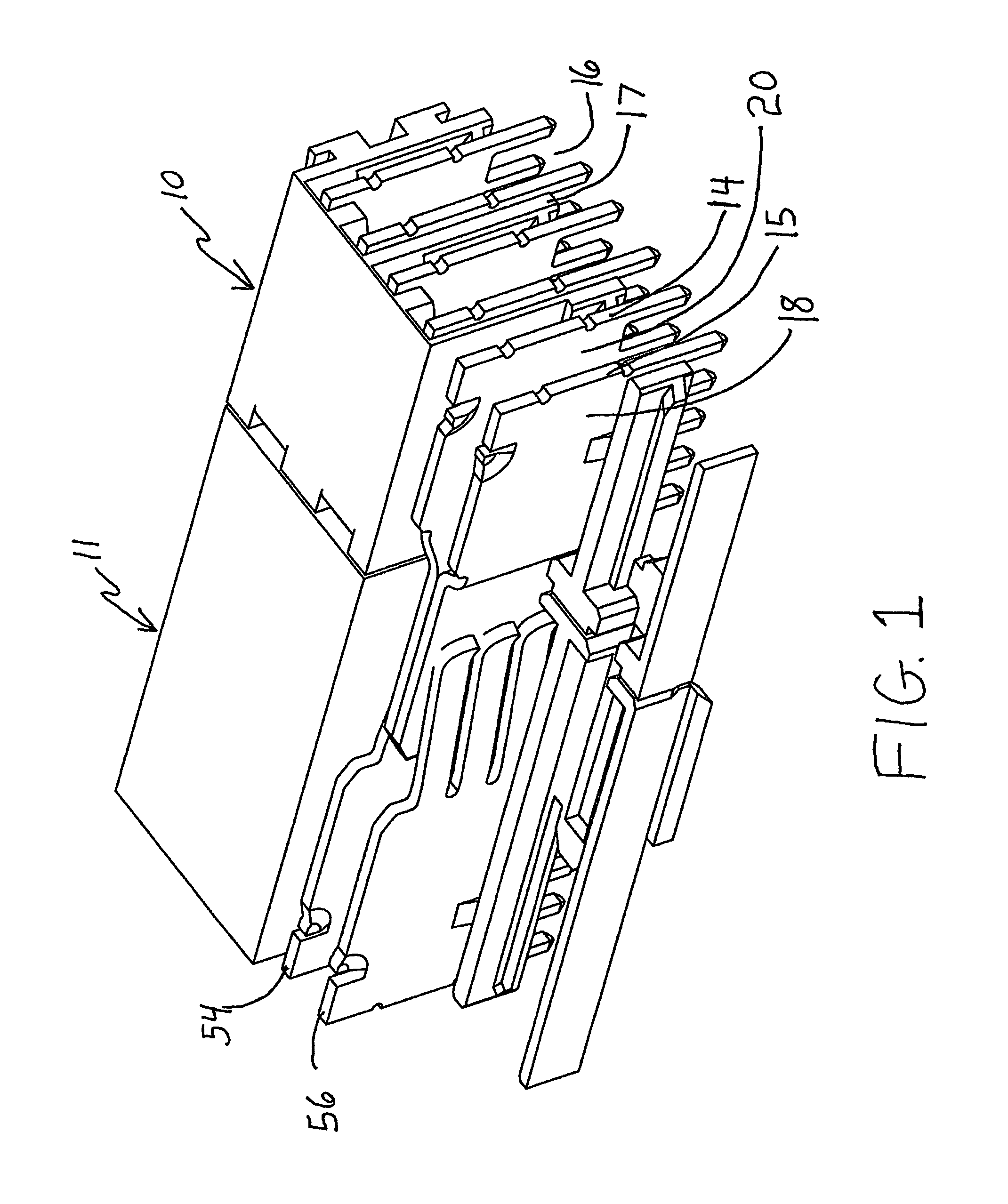
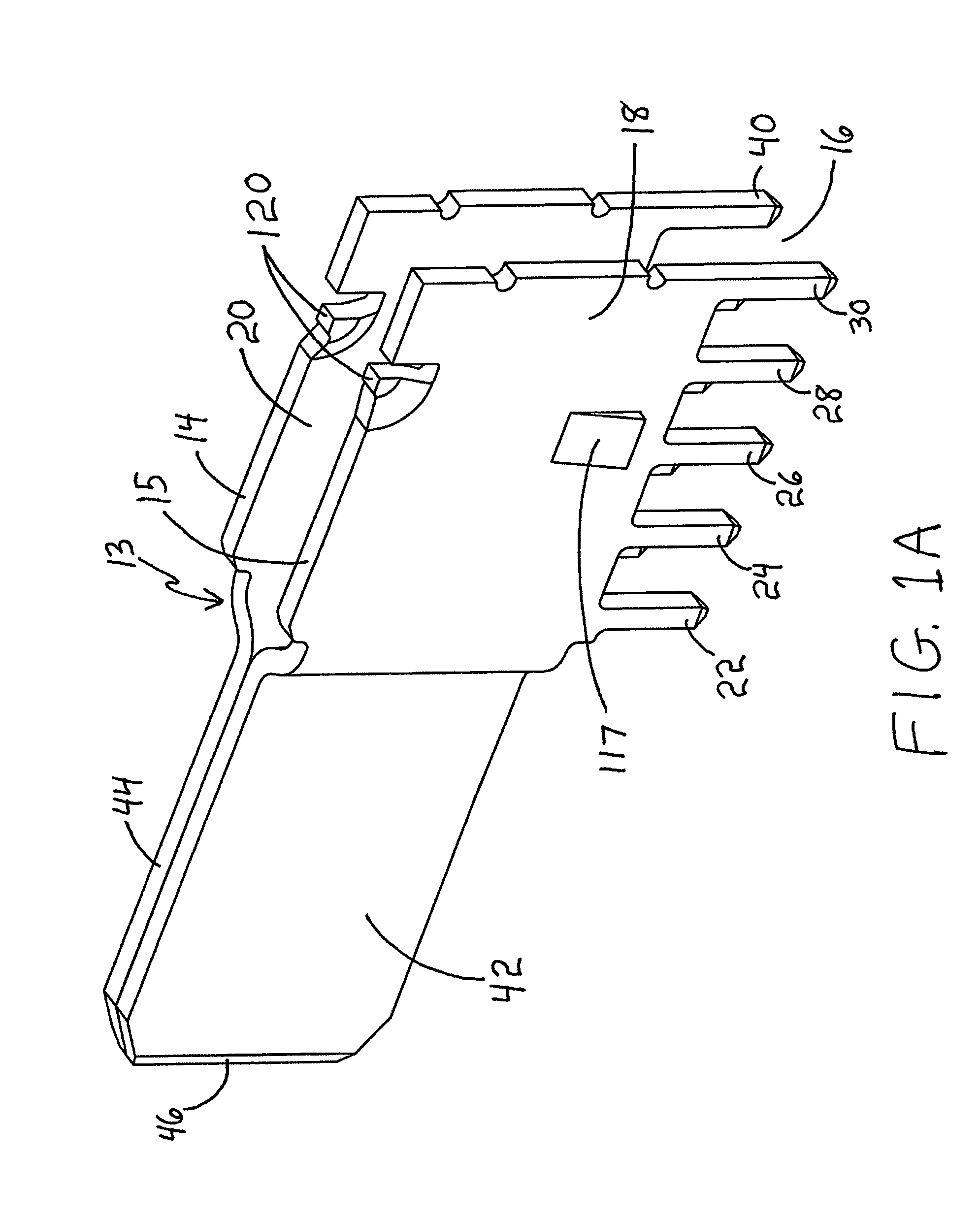
[0039]FIG. 1 illustrates a plug connector, generally designated at 10, and a receptacle connector, generally designated at 11. These are suitable for use as power connector components. The term power connector is meant to encompass AC power connectors and / or DC power connectors. The plug connector 10 illustrated in FIG. 1 includes a contact, generally designated at 13, comprising a pair of mechanically uncoupled contact members, generally designated at 14 and 15. The contact 13 is held in place by ...


PUM


Abstract

Power connector modules are provided that can be plug connectors, receptacle connectors, or a system of plug and receptacle connector modules and optionally other modules, that mate together. Each connector has an uncoupled contact feature. The uncoupled contacts have exposed surfaces to dissipate heat resulting from Joule effects. The uncoupled contacts for the plug connector converge to form a blade structure at one side. The uncoupled contacts for the receptacle connector form a receiving section that engages the blade structure of the plug connector when the plug connector and receptacle connector are used together.

Description

BACKGROUND OF THE INVENTION[0001]The present invention generally relates to electrical power connectors that are useful as low-profile board-to-board connectors and wire-to-board connectors and that can provide excellent operation under high current density conditions and are particularly suitable for use as modular components within modular assemblies.DESCRIPTION OF BACKGROUND ART[0002]It is desired to improve power connectors such as by reducing the size of the connectors and the space they take when connected, for example, to the surface of a board component such as to a printed circuit board (PCB). Increasing current density can contribute to reducing the size of a power connector, but heat generated by the Joule effect can have negative effects. The heat can cause a temperature rise of the contacts that adversely affects electrical characteristics and expands the contacts. With temperature cycling over time, the expansion effects can lead to loosened contacts or other metal com...

Claims


Application Information

Patent Timeline
Patent Type & Authority Patents(United States)
IPC IPC(8): H01R12/00
CPCH01R12/7088
Inventor PATEL, ARVINDKOSTIC, BRATISLAVMCGOWAN, DANIELSTEAD, KENNETHDATA, MARK M.
Owner MOLEX INC
Why Eureka
Try Eureka