Method using block copolymers for making a master mold with high bit-aspect-ratio for nanoimprinting patterned magnetic recording disks

a technology of patterned media and block copolymer, which is applied in the field of making master molds, can solve the problems of difficult and difficult process of master template or mold, and the resolution of e-beam lithography cannot achieve the master mold capable of nano-imprinting patterned media disks with an island pitch of 12.5 nm over an area equal to the data area of a disk, and achieves the effect of ultra-high areal density

Inactive Publication Date: 2011-07-12
WESTERN DIGITAL TECH INC
View PDF17 Cites 37 Cited by
  • Summary
  • Abstract
  • Description
  • Claims
  • Application Information

AI Technical Summary

Problems solved by technology

The making of the master template or mold is a difficult and challenging process.
However, a master mold capable of nanoimprinting patterned-media disks with an island pitch of 12.5 nm over an area equal to the data area of a disk is not achievable with the resolution of e-beam lithography.

Method used


Image

  • Method using block copolymers for making a master mold with high bit-aspect-ratio for nanoimprinting patterned magnetic recording disks
  • Method using block copolymers for making a master mold with high bit-aspect-ratio for nanoimprinting patterned magnetic recording disks
  • Method using block copolymers for making a master mold with high bit-aspect-ratio for nanoimprinting patterned magnetic recording disks

Examples


first embodiment

[0039]A first embodiment of the method of this invention for making the master mold uses conventional optical or e-beam lithography to form a pattern of generally radial stripes on a substrate, with the stripes being grouped into annular zones or bands. A block copolymer material is deposited on the pattern, resulting in guided self-assembly of the block copolymer into its components to multiply the generally radial stripes into generally radial lines of alternating block copolymer components. The radial lines of one of the components are removed, leaving the radial lines of the remaining component to be used as an etch mask to etch the substrate. A protective layer is then deposited over the radial lines of the remaining component to prevent their movement during subsequent processing. Conventional lithography is then used to form concentric rings over the generally radial lines of the remaining component. After etching to remove portions of the remaining block copolymer component ...

second embodiment

[0053]A second embodiment of the method of this invention for making the master mold uses conventional optical or e-beam lithography to form a pattern of generally radial stripes on a substrate, with the stripes being grouped into annular zones or bands. A first block copolymer material with bulk period L0=Lrad is deposited on the pattern, resulting in guided self-assembly of the block copolymer into its components to multiply the generally radial stripes into generally radial lines of alternating block copolymer components. The radial lines of one of the components are removed, leaving the radial lines of the remaining component of the first block copolymer. A protective layer is then deposited over the radial lines of the remaining component of the first block copolymer to prevent their movement during subsequent processing. Then, a second block copolymer material with bulk period L0=Lcirc is deposited over these radial lines to define generally circumferential rings. The circumfe...

third embodiment

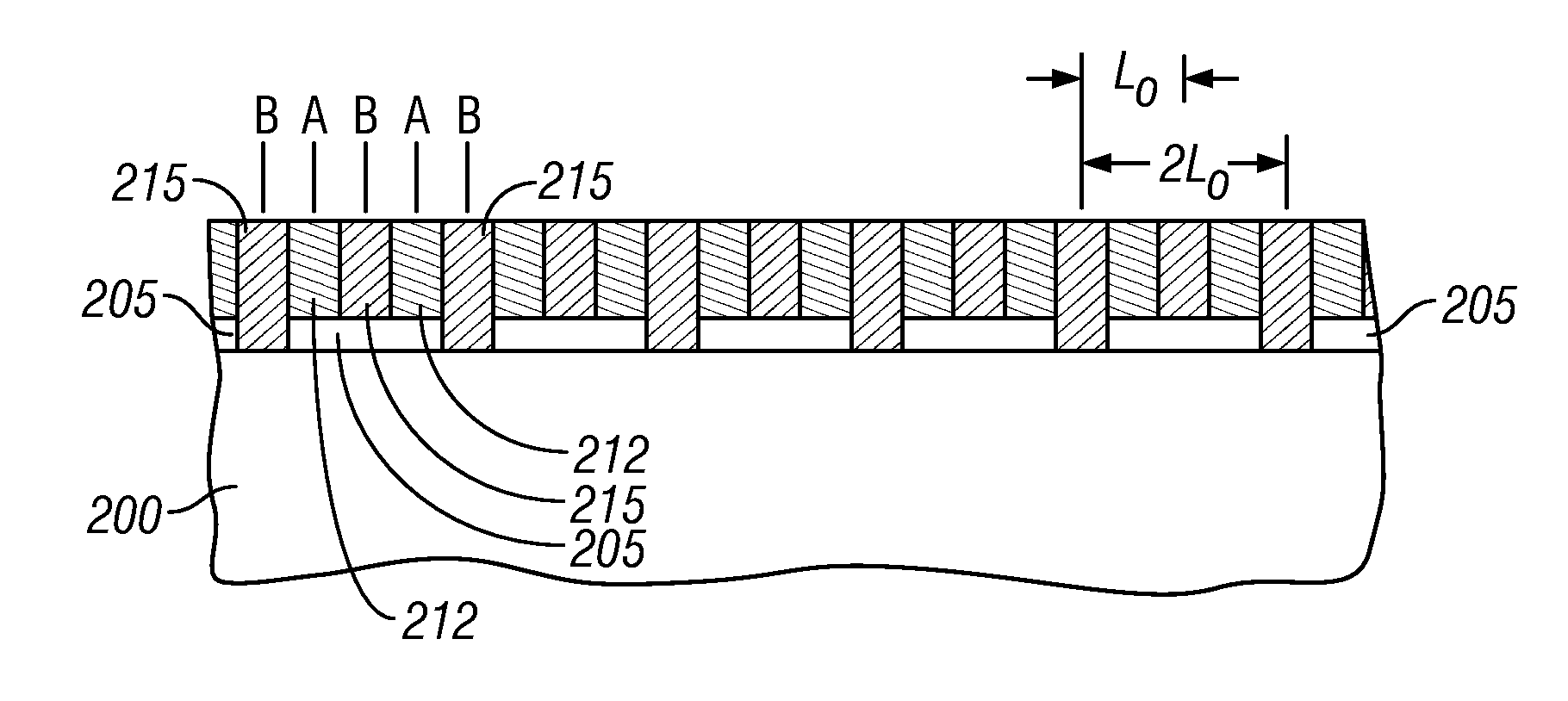
[0059]A third embodiment of the method of this invention for making the master mold uses conventional optical or e-beam lithography to form a pattern of generally radial stripes on a substrate, with the stripes being grouped into annular zones or bands. A block copolymer material with bulk period L0 is deposited on the pattern, resulting in guided self-assembly of the block copolymer into its components to multiply the generally radial stripes into generally radial lines of alternating block copolymer A and B components, as described in the first embodiment. Then an e-beam writer generates a high dose e-beam in a pattern of concentric rings which cross-links the A and B copolymers exposed to the high dose e-beam, resulting in concentric rings formed of cross-linked polymer material. The underlying radial lines of the B component are then removed, leaving the cross-linked concentric rings and underlying radial lines of the A component. This structure then serves as an etch mask to pa...


PUM

PropertyMeasurementUnit
circumferential widthaaaaaaaaaa
ODaaaaaaaaaa
thicknessaaaaaaaaaa

Abstract

A method for making a master mold that is used in the nanoimprinting process to make patterned-media disks with patterned data islands uses guided self-assembly of a block copolymer into its components. Conventional or e-beam lithography is used to first form a pattern of generally radial stripes on a substrate, with the stripes being grouped into annular zones or bands. A block copolymer material is then deposited on the pattern, resulting in guided self-assembly of the block copolymer into its components to multiply the generally radial stripes into generally radial lines. Various methods, including conventional lithography, guided self-assembly of a second block copolymer, and e-beam lithography, are then used to form concentric rings over the generally radial lines. After etching and resist removal, the master mold has a pattern of either pillars or holes, depending on the method used.

Description

RELATED APPLICATION[0001]This application is a continuation-in-part of application Ser. No. 12 / 141,062 filed Jun. 17, 2008.BACKGROUND OF THE INVENTION[0002]1. Field of the Invention[0003]This invention relates generally to patterned-media magnetic recording disks, wherein each data bit is stored in a magnetically isolated data island on the disk, and more particularly to a method for making a master mold to be used for nanoimprinting the patterned-media disks.[0004]2. Description of the Related Art[0005]Magnetic recording hard disk drives with patterned magnetic recording media have been proposed to increase data density. In patterned media, the magnetic recording layer on the disk is patterned into small isolated data islands arranged in concentric data tracks. To produce the required magnetic isolation of the patterned data islands, the magnetic moment of spaces between the islands must be destroyed or substantially reduced to render these spaces essentially nonmagnetic. In one ty...

Claims


Application Information

Patent Timeline
Patent Type & Authority Patents(United States)
IPC IPC(8): C25F3/00B44C1/22G11B5/706
CPCB82Y10/00B82Y40/00G11B5/855G11B5/743G11B5/82G03F7/0002
Inventor DOBISZ, ELIZABETH ANNRUIZ, RICARDO
Owner WESTERN DIGITAL TECH INC
Why Eureka
Try Eureka