LED driving circuit

a driving circuit and led technology, applied in the direction of electric variable regulation, process and machine control, instruments, etc., can solve the problems of unfavorable increase in the cost of constant current drivers, and achieve the effect of effectively reducing circuit costs

Inactive Publication Date: 2011-07-12
GREEN SOLUTION TECH CO LTD
View PDF7 Cites 22 Cited by
  • Summary
  • Abstract
  • Description
  • Claims
  • Application Information

AI Technical Summary

Benefits of technology

[0006]In view of the aforementioned issues in prior art, the present invention can raise the upper limit for the level of the driving signal for driving the transistor switch in the LED driving circuit, such that the maximum load current of the transistor switch is accordingly increase. Compared with prior art, the present invention can use the transistor switch of smaller die size to satisfy the same driving current request, thereby effectively reducing circuit cost.

Problems solved by technology

In case that the LED driving device needs to be driven with greater current, and the level of the driving signal outputted by the error amplifier 12 is to be limited under the level of the drain D, it is inevitable to enlarge the die size of the transistor switch 14, causing undesirable increase in the cost of the constant current driver.

Method used


Image

  • LED driving circuit
  • LED driving circuit
  • LED driving circuit

Examples


Embodiment Construction

[0013]The current formula of Metal Oxide Semiconductor Field Effect Transistor (MOSFET) can be shown as below:

[0014]Id=12⁢μ0⁢Cox⁢WL⁢(Vgs-Vt)2

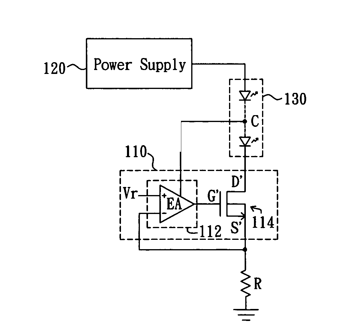
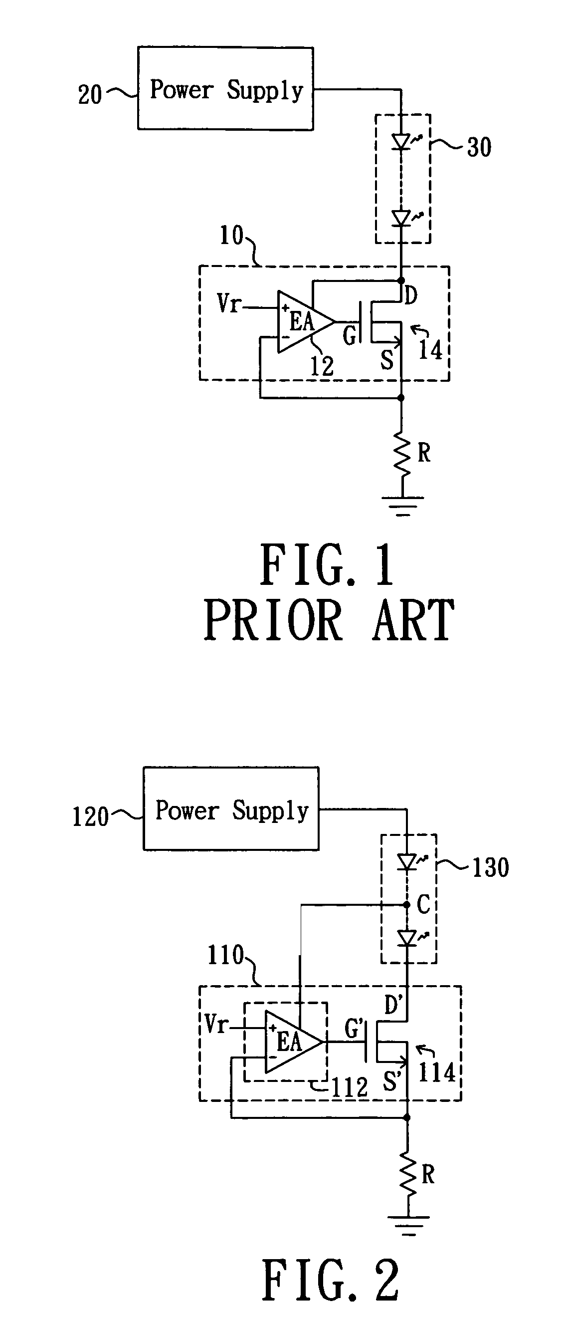
[0015]Accordingly, to increase current while maintaining the W / L ratio at the same time; that is, without enlarging the die size (W) of the transistor, it is required to raise the gate-source voltage Vgs.

[0016]Refer now to FIG. 2, a circuit diagram for an LED driving device of a preferred embodiment according to the present invention is shown. The depicted LED driving device comprises a constant current driver 110, a power supply 120, an LED module 130, and a current detecting resistor R. The constant current driver 110 comprises a feedback controller 112 and a transistor switch 114. The power supply 120 provides a driving current flowing through the LED module 130, the constant current driver 110, and the current detecting resistor R, in which the current detecting resistor R generates a current detecting signal indicating the magnitude of the...


PUM


Abstract

An LED driving circuit is provided for driving an LED module, comprising a transistor switch and a feedback controller. The transistor switch has a control terminal, a first terminal, and a second terminal. The first terminal is coupled to the LED module and the control terminal receives a control signal for controlling a current passing through the transistor switch. The feedback controller receives a reference voltage and a current detecting signal indicative of the magnitude of the current and generates the control signal accordingly. The feedback controller is connected to a driving power source with level higher than the level of the first terminal of the transistor switch. Hence, the maximum level of an adjustable range of the control signal is higher than the first terminal of the transistor switch.

Description

BACKGROUND OF THE INVENTION[0001]1. Field of the Invention[0002]The present invention relates to a Light Emitting Diode (LED) driving circuit; in particular, to a LED driving circuit driven by constant current.[0003]2. Description of Related Art[0004]Referring to FIG. 1, which shows a prior art LED driving device. The LED driving device comprises a constant current driver 10, a power supply 20, an LED module 30, and a current detecting resistor R. The constant current driver 10 comprises an error amplifier 12 and a transistor switch 14. The power supply 20 provides a driving current flowing through the LED module 30, the constant current driver 10, and the current detecting resistor R. The current detecting resistor R generates a current detecting signal indicating the magnitude of the driving current. An inverting terminal of the error amplifier 12 receives the current detecting signal, and a non-inverting terminal of the error amplifier 12 receives a reference voltage Vr, so that ...

Claims


Application Information

Patent Timeline
Patent Type & Authority Patents(United States)
IPC IPC(8): G05F1/00
CPCH05B33/0812Y02B20/345H05B45/395Y02B20/30
Inventor SHIU, SHIAN-SUNGYU, CHUNG-CHE
Owner GREEN SOLUTION TECH CO LTD
Why Eureka
Try Eureka