Method and apparatus for modifying right half-plane zero in a cascaded DC-DC buck-boost converter

a buck-boom converter and buck-boom technology, applied in the direction of dc-dc conversion, power conversion systems, instruments, etc., can solve the problems of initial decrease in output, drop in output current, and decrease in discharge time of inductor, so as to increase the converter bandwidth

Inactive Publication Date: 2011-07-12
MICROSEMI CORP
View PDF7 Cites 29 Cited by
  • Summary
  • Abstract
  • Description
  • Claims
  • Application Information

AI Technical Summary

Problems solved by technology

Unfortunately, in an initial stage, the output current drops.
However, until a full switching cycle has passed, the increase in duty cycle results in a decreased discharge time for the inductor, since a period of the switching cycle does not change.
The decreased discharge time results in an initial decrease in the output which reinforces the decrease in the output due to the increased load.
The need for such a low frequency dominant pole places an upper limit on a dynamic performance of the converter.

Method used


Image

  • Method and apparatus for modifying right half-plane zero in a cascaded DC-DC buck-boost converter
  • Method and apparatus for modifying right half-plane zero in a cascaded DC-DC buck-boost converter
  • Method and apparatus for modifying right half-plane zero in a cascaded DC-DC buck-boost converter

Examples


Embodiment Construction

[0017]Before explaining at least one embodiment of the invention in detail, it is to be understood that the invention is not limited in its application to the details of construction and the arrangement of the components set forth in the following description or illustrated in the drawings. The invention is applicable to other embodiments or of being practiced or carried out in various ways. Also, it is to be understood that the phraseology and terminology employed herein is for the purpose of description and should not be regarded as limiting.

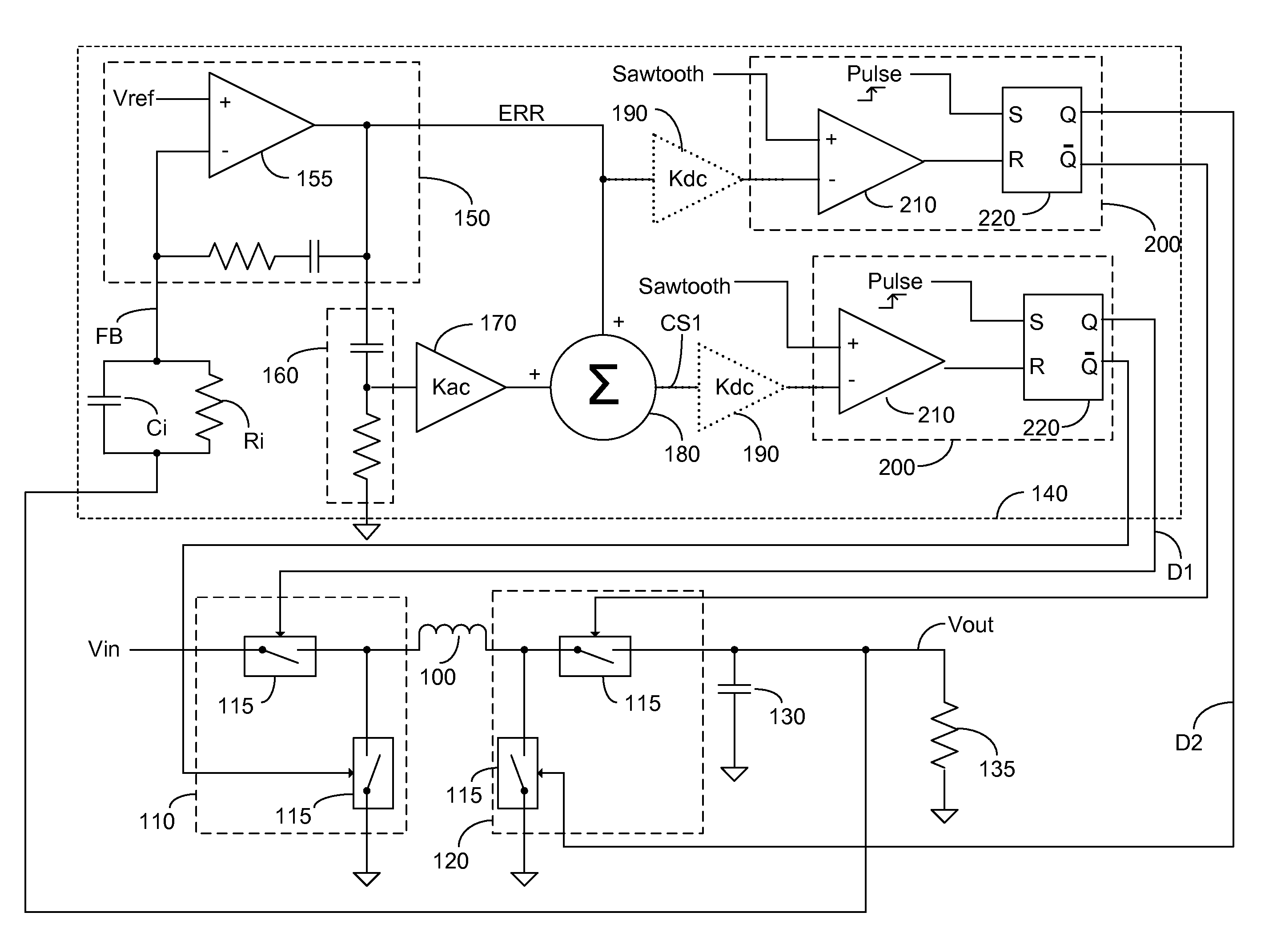
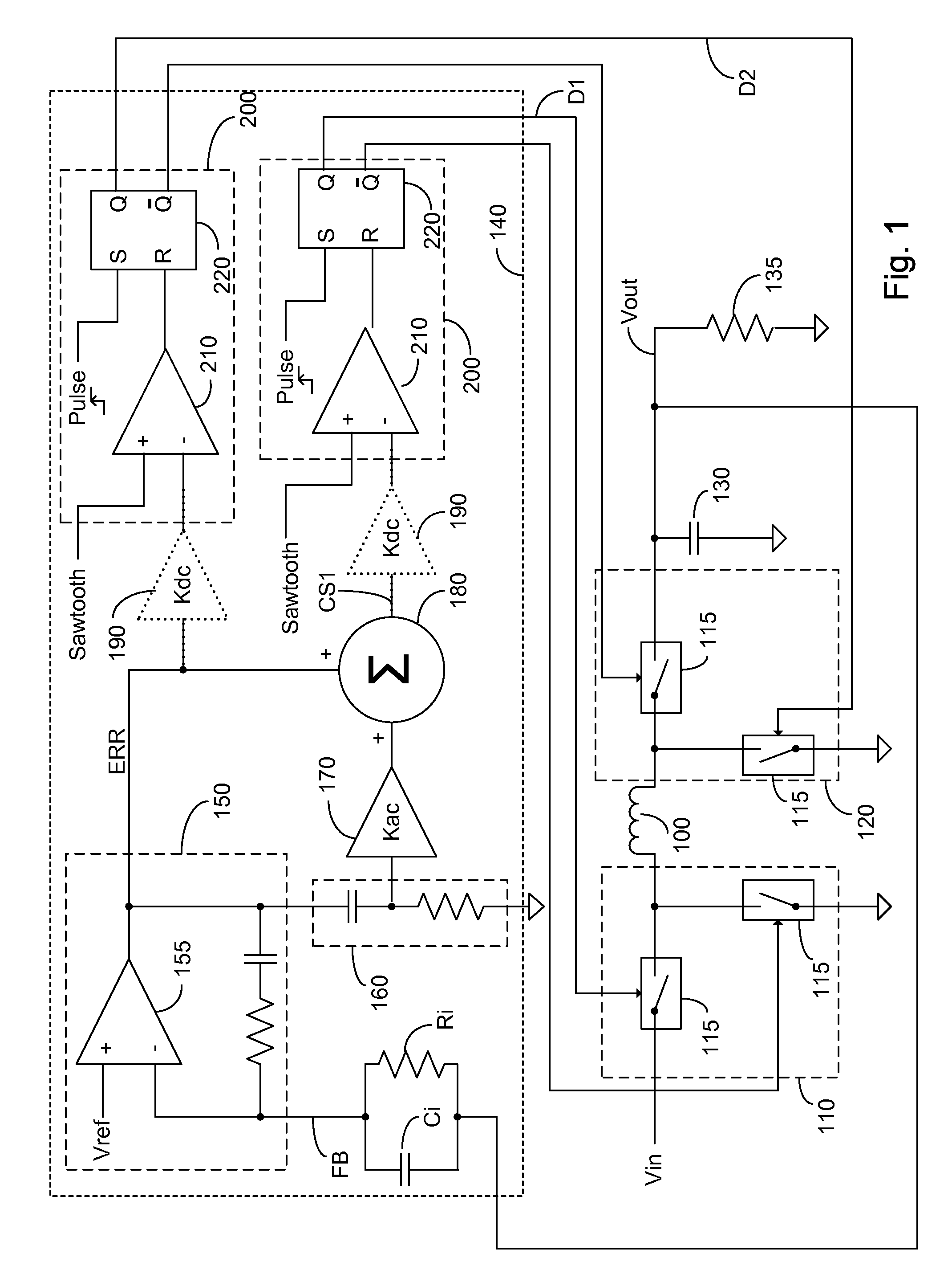
[0018]FIG. 1 is a simplified schematic diagram of an exemplary embodiment of a cascaded DC-DC buck-boost converter with means for modifying a RHPZ in a transfer function to improve stability over a wider range of frequencies comprising a high pass filter, where both the boost function and the buck function are implemented with a pair of electronically controlled switches. The cascaded DC-DC buck-boost converter comprises: an energy storage ele...


PUM


Abstract

A method to generate a substantially DC output having a voltage level different than a DC input, constituted of receiving a feedback signal representing at least one of the voltage level and the current level of the generated substantially DC output; relatively emphasizing the high frequency portion of the feedback signal; controlling the buck function of a cascaded buck-boost converter with a first switching signal having a first duty cycle, the first duty cycle being a first function of the received feedback signal responsive to said relatively emphasized high frequency portion; and controlling the boost function with a second switching signal having a second duty cycle, the second duty cycle being a second function of the received feedback signal, wherein the first switching signal and the second switching signal are continuously enabled to facilitate a continuous conduction mode.

Description

FIELD OF THE INVENTION[0001]This invention relates to a DC-DC power converter and more particularly to a means for improving a loop bandwidth of the DC-DC power converter by emphasizing the high frequency section of the feedback signal controlling the buck portion of the cascaded buck-boost converter.BACKGROUND OF THE INVENTION[0002]A boost converter, also known as a step-up converter, is a power converter with an output DC voltage greater than its input DC voltage. It is a class of switching-mode power supply containing at least a first electronically controlled switch (e.g., a transistor), at least a first energy storage element (e.g., an inductor), and an additional element such as a diode or a second electronically controlled switch. Typically, the electronically controlled switches and diode are arranged between the inductor and the output, with current being alternately drawn to charge the inductor responsive to the first electronically controlled switch being closed, and pass...

Claims


Application Information

Patent Timeline
Patent Type & Authority Patents(United States)
IPC IPC(8): G05F1/40G05F1/10
CPCH02M3/1582
Inventor FAHRENBRUCH, SHAWN ANTHONYKAHN, SIMON
Owner MICROSEMI CORP
Why Eureka
Try Eureka