
Low impedance series coupled radio frequency directional power detector

a directional power detector and low impedance technology, applied in the field of radio frequency directional power detectors, can solve the problems of reducing the forward power fed into the antenna, directional couplers may present an unacceptably high impedence in series with the low output impedance of power amplifiers, and traditional directional couplers may have difficulty in distinguishing forward from reverse power

Active Publication Date: 2011-07-12
QORVO US INC
View PDF12 Cites 14 Cited by
  • Summary
  • Abstract
  • Description
  • Claims
  • Application Information

AI Technical Summary

Benefits of technology

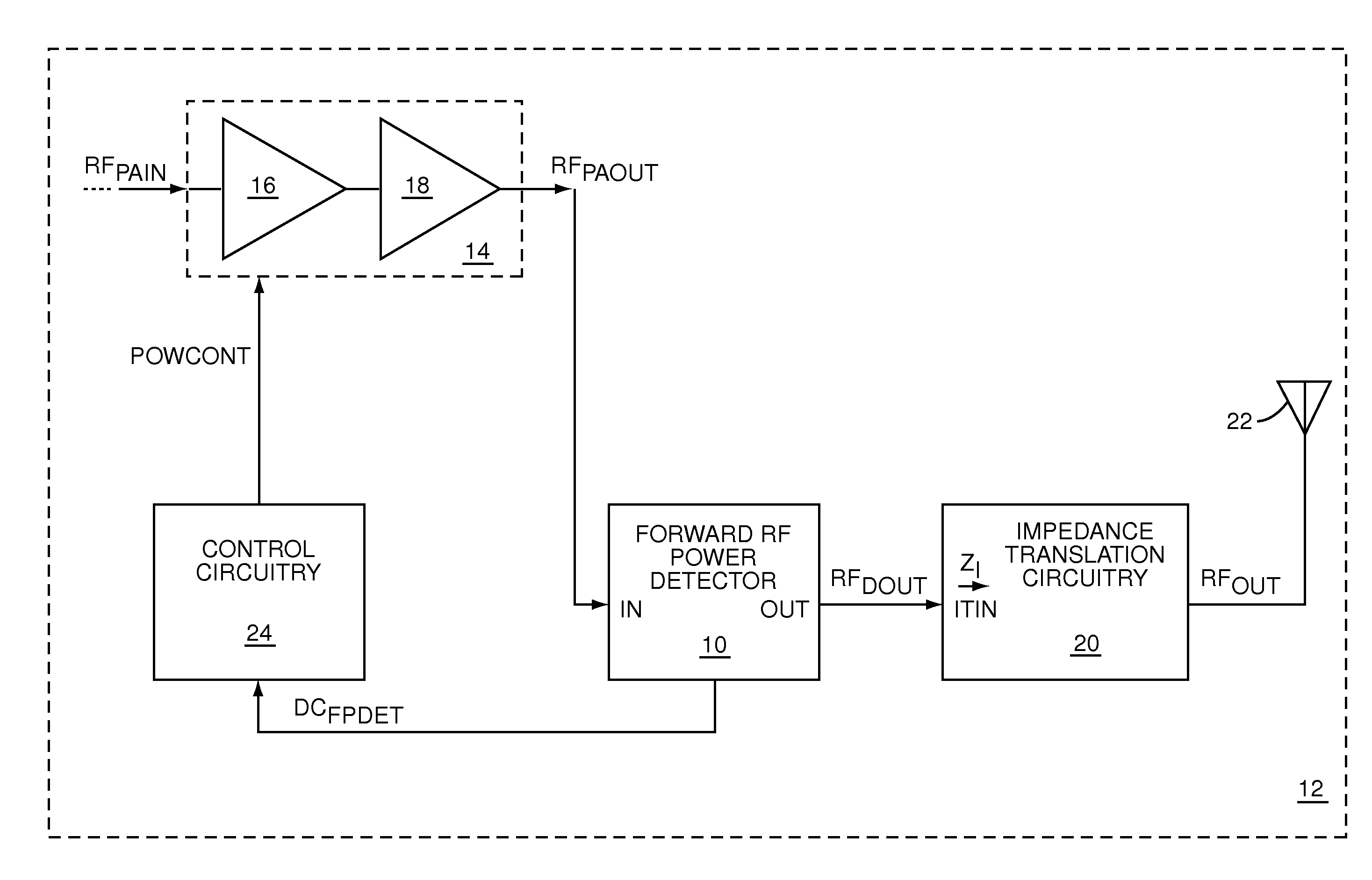
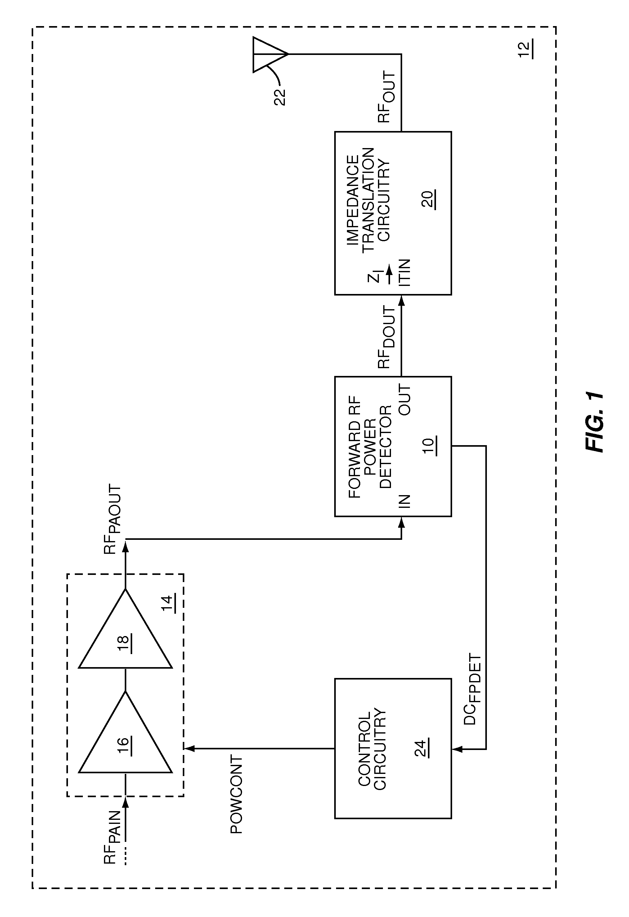
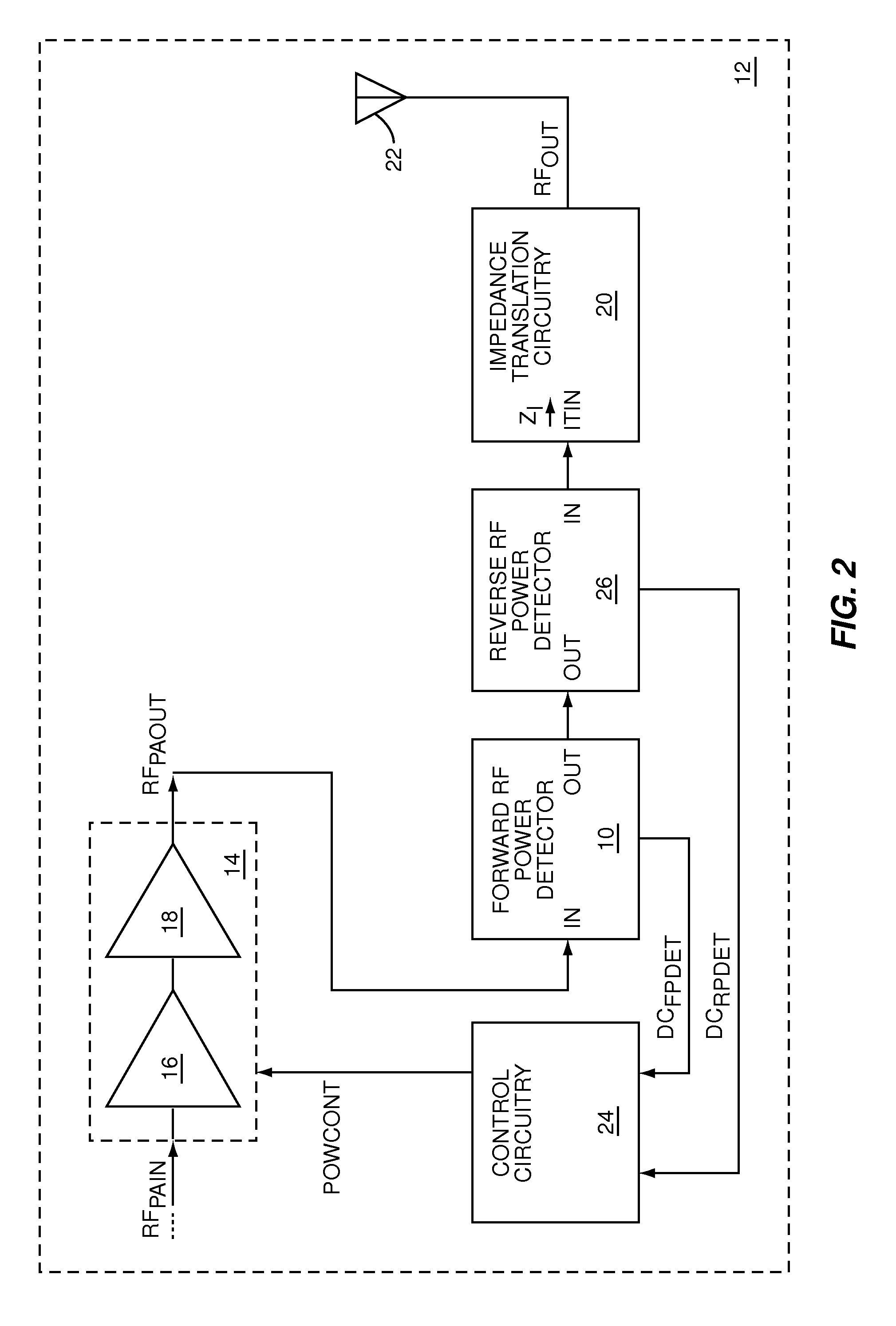
[0006]The present invention is a low series impedance directional power detector, which may be used to measure either forward or reverse power in an RF circuit. The directional power detector includes current detection circuitry to directionally measure current, voltage detection circuitry to measure voltage, and combining circuitry to combine the directional RF current measurements and the RF voltage measurements into a combined RF measurement, which is indicative of directional power. The current detection circuitry and voltage detection circuitry apply any phase-shifts that are needed to detect power in the direction of interest and ignore power in the opposite direction when the directional power detector is presented with a complex load.

Problems solved by technology

These impedance variations and resulting VSWR variations may reduce the delivered power from the power amplifier and may reflect a portion of the delivered power back to the power amplifier, thereby reducing the forward power fed into the antenna.
Coupling the directional coupler between the power amplifier and the impedance matching circuitry may eliminate the need for the harmonics filtering; however, a traditional directional coupler may present an unacceptably high impedence in series with the low output impedance of the power amplifier.
Traditional directional couplers may have difficulty differentiating forward from reverse power when presented with a complex load impedance, such as that presented by impedance matching circuitry.

Method used


Image

  • Low impedance series coupled radio frequency directional power detector
  • Low impedance series coupled radio frequency directional power detector
  • Low impedance series coupled radio frequency directional power detector

Examples


first embodiment

[0030]FIG. 5 shows the combining circuitry 32 illustrated in FIG. 3. The combining circuitry 32 includes a summing circuit 36, which has a first input IN1 that receives the RF current detection signal RFIDET, a second input IN2 that receives the RF voltage detection signal RFVDET, and a summing output SOUT that provides the RF power detection signal RFPDET, which is approximately equal to the sum of the RF current detection signal RFIDET and the RF voltage detection signal RFVDET.

second embodiment

[0031]FIG. 6 shows the combining circuitry 32 illustrated in FIG. 3. The combining circuitry 32 includes a difference circuit 38, which has a third input IN3 that receives the RF current detection signal RFIDET, a fourth input IN4 that receives the RF voltage detection signal RFVDET, and a difference output DOUT that provides the RF power detection signal RFPDET, which is approximately equal to a difference between the RF current detection signal RFIDET and the RF voltage detection signal RFVDET.

[0032]FIG. 7 adds a current detection circuit 40 and a phase-shift circuit 42 to the current detection circuitry 28 illustrated in FIG. 5. The current detection circuit 40 provides a current detection signal that is based on the RF input current IRFIN, the RF output current IRFOUT, or both, to the phase-shift circuit 42, which applies a phase-shift to provide the RF current detection signal RFIDET. In one embodiment of the present invention, the phase-shift provided by the phase-shift circui...


PUM


Abstract

The present invention is a low series impedance directional power detector, which may be used to measure either forward or reverse power in a radio frequency (RF) circuit. The directional power detector includes current detection circuitry to directionally measure current, voltage detection circuitry to measure voltage, and combining circuitry to combine the directional RF current measurements and the RF voltage measurements into a combined RF measurement, which is indicative of directional power. The current detection circuitry and voltage detection circuitry apply any phase-shifts that are needed to detect power in the direction of interest and ignore power in the opposite direction when the directional power detector is presented with a complex load.

Description

[0001]This application claims the benefit of provisional patent application Ser. No. 60 / 825,471, filed Sep. 13, 2006, the disclosure of which is hereby incorporated by reference in its entirety.FIELD OF THE INVENTION[0002]The present invention relates to radio frequency (RF) directional power detectors used in RF communications circuitry, such as RF transmitters and RF receivers.BACKGROUND OF THE INVENTION[0003]The radiated output power of mobile terminals, such as mobile phones, Personal Digital Assistants (PDAs), and the like, is based on forward power provided to an antenna by a power amplifier. The forward power is a function of the total power delivered by the power amplifier minus any power reflected back from the antenna due to impedance mismatches from the power amplifier to the antenna. The relationship of forward power to reflected, or reverse, power may be characterized using a voltage standing wave ratio (VSWR). For an open loop power amplifier, the total delivered power...

Claims


Application Information

Patent Timeline
Patent Type & Authority Patents(United States)
IPC IPC(8): G01R31/08
CPCG01R21/07
Inventor JONES, DAVID E.SCHOOLEY, DEREKMAINS, NEAL
Owner QORVO US INC
Learn More